


1
1
2
2
3
3
4
4
5
5
6
6
D
D
C
C
B
B
A
A
GND
VDDI
VDDI
GND
GND
GND
GND
C40
2.2uF-0402-X5R-±20%-6.3V
C37
0.1uF-0402-X5R-±20%-16V
C38
NC/0.1uF-0402-X5R-±20%-16V
C34
2.2uF-0402-X5R-±20%-6.3V
C35
0.1uF-0402-X5R-±20%-16V
GND
GND
C36
0.1uF-0402-X5R-±20%-16V
R31
10Kohm-0402-±5%-1/16W
3V3_M
3V3_M
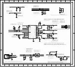
1V8_EMMC
EMMC_D0_IO_IC
EMMC_D1_IO_IC
EMMC_D2_IO_IC
EMMC_D3_IO_IC
EMMC_D4_IO_IC
EMMC_D5_IO_IC
EMMC_D6_IO_IC
EMMC_D7_IO_IC
EMMC_D5_IO_IC
EMMC_D5_IO_IC
EMMC_D3_IO_IC
EMMC_D4_IO_IC
EMMC_D6_IO_IC
EMMC_D7_IO_IC
GND
GND
EMMC_DS_IO_IC
R43
10Kohm-0402-±5%-1/16W
EMMC_RSTN_IN_IC
R44
NC/10Kohm-0402-±5%-1/16W
R45
10Kohm-0402-±5%-1/16W
EMMC_CLK_IN_IC
EMMC_CMD_IN_IC
R6
10Kohm-0402-±5%-1/16W
R11
10Kohm-0402-±5%-1/16W
R21
10Kohm-0402-±5%-1/16W
R22
10Kohm-0402-±5%-1/16W
R23
10Kohm-0402-±5%-1/16W
R27
10Kohm-0402-±5%-1/16W
R28
10Kohm-0402-±5%-1/16W
R29
10Kohm-0402-±5%-1/16W
EMMC_D4_IO_IC
EMMC_D5_IO_IC
EMMC_D6_IO_IC
EMMC_D7_IO_IC
EMMC_D0_IO_IC
EMMC_D1_IO_IC
EMMC_D2_IO_IC
EMMC_D3_IO_IC
C47
0.1uF-0402-X5R-±20%-16V
C39
22uF-0603-X5R-±20%-6.3V
C33
22uF-0603-X5R-±20%-6.3V
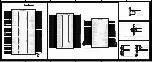
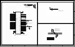
VDD
K9
VDD
J10
VDD
F5
VDD
E6
VDD_IF
P3
VDD_IF
P5
VDD_IF
N4
VDD_IF
M4
VDD_IF
C6
CREG/VDDi
C2
VSS
C4
CLK
M6
CMD
M5
D0
A3
D1
A4
D2
A5
D3
B2
VSS
E7
VSS
G5
VSS
H10
VSS
K8
VSS
N2
VSS
N5
VSS
P4
VSS
P6
D4
B3
D5
B4
D6
B5
D7
B6
RESET
K5
ERR
F3
ERR
G2
ERR
G1
ERR
D4
ERR
E3
ERR
F2
ERR
F1
ERR
E1
ERR
E2
ERR
D3
ERR
D1
ERR
D2
ERR
C3
ERR
C1
ERR
A2
ERR
B7
ERR
A8
ERR
N7
ERR
P8
ERR
M8
ERR
N9
ERR
P9
ERR
M9
ERR
N10
ERR
P11
ERR
N1
Vss
A6
VSF
E9
VSF
E10
VSF
F10
DS
H5
Vss
J5
ERR
A1
ERR
C5
ERR
M1
ERR
M2
ERR
C7
ERR
B8
ERR
A9
ERR
A10
ERR
B9
ERR
C8
ERR
P7
ERR
N6
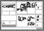
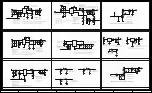
RT2841
方案
特殊使用
U3
客供
EMMC FLASH
芯片
,IC EMMC FLASH,SMD,H26M41204HPR,TCL-TOT,SKhynix
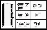
EMMC_D6_IO_IC
C64
NC/22uF-0603-X5R-±20%-6.3V
C65
22uF-0603-X5R-±20%-6.3V
C66
NC/0.1uF-0402-X5R-±20%-16V
C67
NC/22uF-0603-X5R-±20%-6.3V
1V8_EMMC
1V8_EMMC
1V8_EMMC
1V8_EMMC
EMMC_DS_IO_IC
EMMC_DS_IO_IC
EMMC_CMD_IN_IC
EMMC_CMD_IN_IC
EMMC_CLK_IN_IC
EMMC_CLK_IN_IC
EMMC_RSTN_IN_IC
EMMC_RSTN_IN_IC
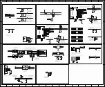
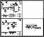
Summary of Contents for RT41VS-EU
Page 32: ...Test and Alignment Specification for RT2841 Series v0 01 docx Page 27 of 27...
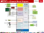
Page 33: ...11 Oct 18 Page 8 nRT41 Chassis Block Diagram...
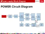
Page 34: ...11 Oct 18 Page 9 nPower supply Block Diagram...
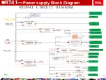
Page 35: ...11 Oct 18 Page 10 nRT41 Power supply Block Diagram...
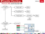
Page 46: ...11 Oct 18 Page 23 nTrouble Shooting...
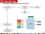
Page 47: ...nTrouble Shooting 11 Oct 18 Page 24...
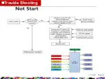
Page 48: ...nTrouble Shooting 11 Oct 18 Page 25...
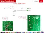
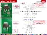
Page 49: ...11 Oct 18 Page 11 nKey Test Point Main Power Supply 12V 12V Test point...
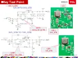
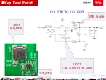
Page 51: ...11 Oct 18 Page 13 nKey Test Point LDC1 1V5_DDR UDC1 3V3_STB to 1V5_DDR 3V3_STB STR Enable...
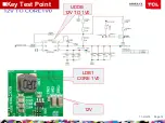
Page 52: ...11 Oct 18 Page 14 LDB1 CORE 1V0 nKey Test Point 12V UDDB 12V TO 1V0...
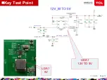
Page 53: ...11 Oct 18 Page 15 LDA1 5V nKey Test Point UDA1 12V TO 5V...
Page 57: ...11 Oct 18 Page 19 nKey Test Point PANEL_VCC 12V Q900 PANEL_VCC...
Page 58: ...11 Oct 18 Page 20 Main Chip 1 SOC Config 2 24MHz CRYSTAL nKey Test Point Test Point...