


Test and Alignment Specification for RT2841 Series (v0.01).docx
Page 14 of 27
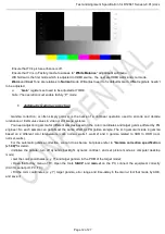
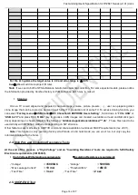
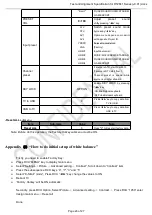
For the 4+3 gamma the target value is 2.2 and error range is
±
0.05.
Note
④:
We will add more project ID later.
Note
:
If we can do both of White Balance & Automatic Gamma correction. For some special models, please notice
the information provided by Huizhou factory or PJM to choose which way to make it.
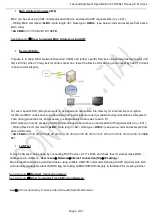
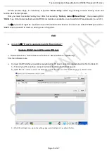
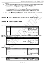
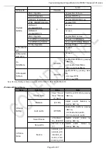
Cloning
Once a TV is well aligned and prepared (channels maps, volume, picture presets, …) , user can prepare golden
clone image that can be copied on demand to all further TV production lot of same TV. To access cloning function, you
can select “
Factory menu
USB Clone
All / Chanel List/ EEPROM/ Users Setting
” , Scroll down to “
TV to USB
” or
“
USB to TV
” and press RCU “
OK/
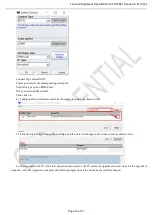
►” key to process. 4 BIN images can created, overwritten or read on USB stick (pen
drive) depending on chosen template like following: “
database\applications\database\***.db
” . These files need to be
used strictly with MT58SoC platform as depending on SW structure.
Other faster access methods via UART/IR command share available on enclosed SIACP requirements (rev. v8.31).
Note
: This function is only useful on factory sita P mode. And in hotel mode, we can use it too, but only copy the
information related to the hotel.
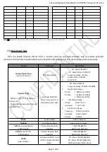
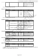
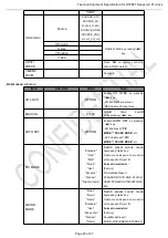
2.4.High Pot. and Insulating Resistance Tests
At the end of the process, a “High Voltage” and an “Insulating Resistance” tests are required to fulfill Safety
Electrical requirements (CEI 65065).
High Voltage Withstanding requirements
Insulating Resistance requirements
- “Voltage”
3500VAC
- “Voltage”
500VDC
- “Max Leakage Current”
10 mA
- “Threshold Min”
4M Ω
- “Test Time”
3 sec
- “Test Time”
2 sec
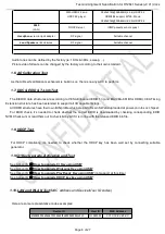
2.5.SHOP-END Test
Summary of Contents for RT41VS-EU
Page 32: ...Test and Alignment Specification for RT2841 Series v0 01 docx Page 27 of 27...
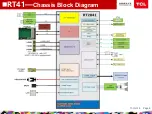
Page 33: ...11 Oct 18 Page 8 nRT41 Chassis Block Diagram...
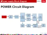
Page 34: ...11 Oct 18 Page 9 nPower supply Block Diagram...
Page 35: ...11 Oct 18 Page 10 nRT41 Power supply Block Diagram...
Page 46: ...11 Oct 18 Page 23 nTrouble Shooting...
Page 47: ...nTrouble Shooting 11 Oct 18 Page 24...
Page 48: ...nTrouble Shooting 11 Oct 18 Page 25...
Page 49: ...11 Oct 18 Page 11 nKey Test Point Main Power Supply 12V 12V Test point...
Page 51: ...11 Oct 18 Page 13 nKey Test Point LDC1 1V5_DDR UDC1 3V3_STB to 1V5_DDR 3V3_STB STR Enable...
Page 52: ...11 Oct 18 Page 14 LDB1 CORE 1V0 nKey Test Point 12V UDDB 12V TO 1V0...
Page 53: ...11 Oct 18 Page 15 LDA1 5V nKey Test Point UDA1 12V TO 5V...
Page 57: ...11 Oct 18 Page 19 nKey Test Point PANEL_VCC 12V Q900 PANEL_VCC...
Page 58: ...11 Oct 18 Page 20 Main Chip 1 SOC Config 2 24MHz CRYSTAL nKey Test Point Test Point...


