


42
Models C708 & C716
Operating Procedures
080617
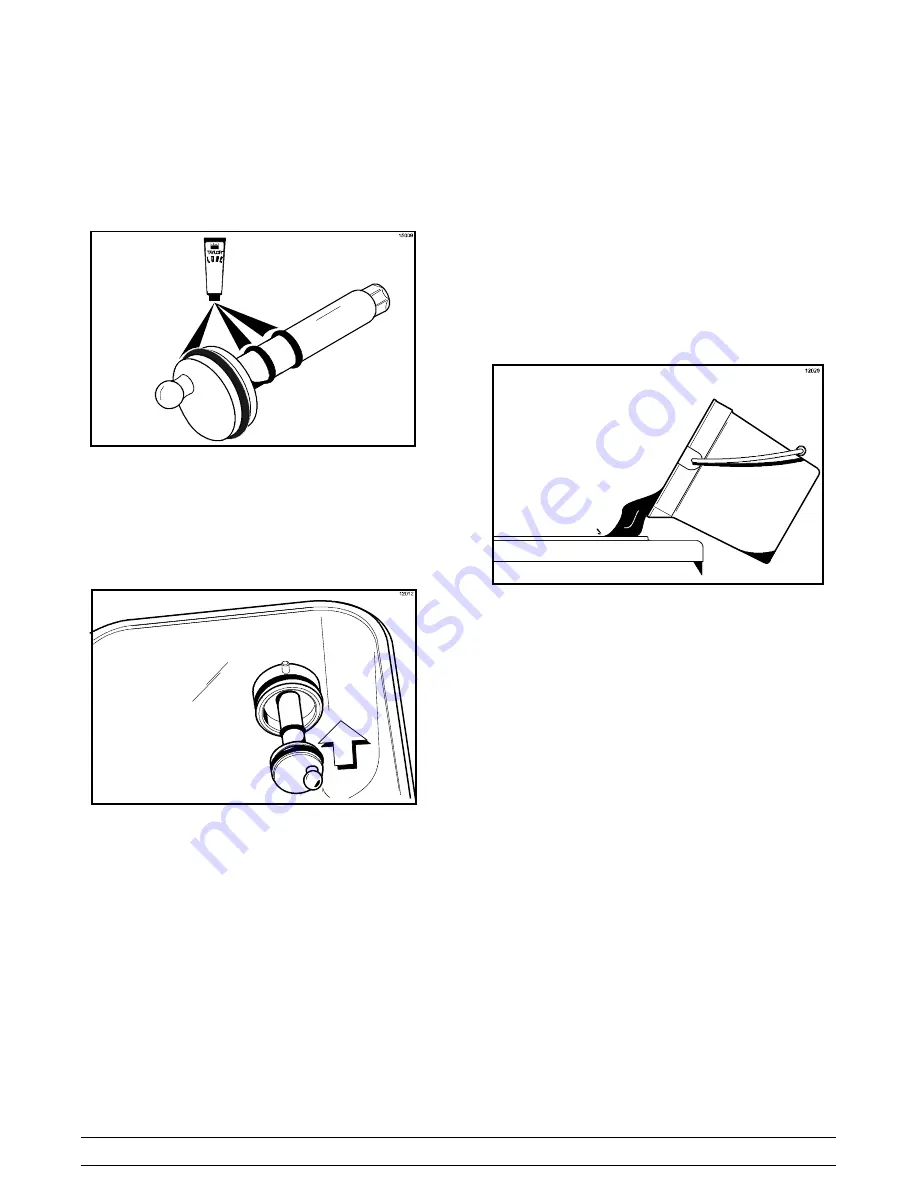
Step 13
Slide the large black o-ring and the two smaller
black o-rings into the grooves on the drive shaft.
Thoroughly lubricate the o-rings and shaft. DO NOT
lubricate the hex end of the shaft. (See Figure 47.)
Figure 47
Step 14
Install the hex end of the drive shaft into the drive
hub at the rear wall of the mix hopper.
(See Figure 48.)
Figure 48
Note:
For ease in installing the pump, position the
ball crank of the drive shaft in the 3 o'clock position.
Repeat these steps for the other side of the
Model C716.
Sanitizing
Step 1
Prepare an approved 100 PPM sanitizing solution
(examples: 2-1/2 gal. [9.5 liters] of Kay-5
R
or 2
gal. [7.6 liters] of Stera-Sheen
R
). USE WARM WA-
TER AND FOLLOW THE MANUFACTURER'S
SPECIFICATIONS.
Step 2
Pour the sanitizing solution over all the parts in the
bottom of the mix hopper and allow it to flow into the
freezing cylinder. (See Figure 49.)
Figure 49
Note:
You have just sanitized the mix hopper and
parts; therefore, be sure your hands are clean and
sanitized before going on in these instructions.
Step 3
While the solution is flowing into the freezing
cylinder, take particular care to brush-clean the mix
level sensing probe on the bottom of the hopper, the
mix hopper, the mix inlet hole, the air/mix pump, the
pump clip, the mix feed tube, and the locking clip.
Step 4
Install the pump assembly at the rear of the mix
hopper. To position the pump on the drive hub, align
the drive hole in the piston with the drive crank of
the drive shaft. Secure the pump in place by slipping
the pump clip over the collar of the pump, making
sure the clip fits into the grooves in the collar.
(See Figure 50.)


