THDC / THDCP - 954 / 955 / 974 (Rev. 06/03)
THDC / THDCP - 954 / 955 / 974 (Rev. 06/03)
6-6
6-6
1
1
5
5
14
14
13
13
9
9
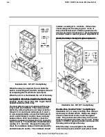
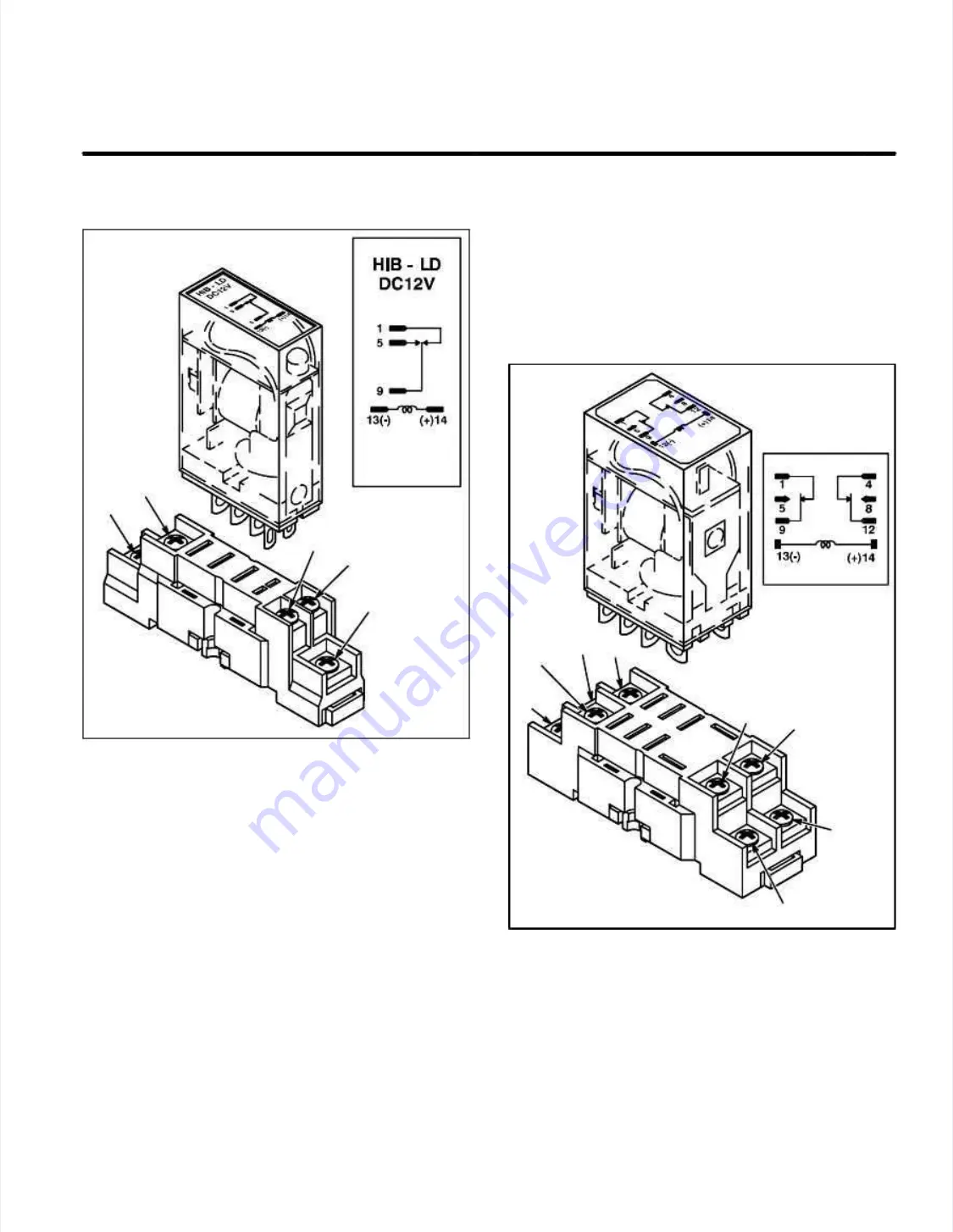
Illust
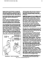
Illustration 6-5.
ration 6-5. SP
SP, ST 10 amp Relay
, ST 10 amp Relay
When the relay is energized, the coil shifts the
When the relay is energized, the coil shifts the
switch, connecting pins (9 and 5) and pins (12 and
switch, connecting pins (9 and 5) and pins (12 and
8) completing the circuit of both sets of pins.
8) completing the circuit of both sets of pins.
When the L.E.D. is illuminated, the coil of the relay
When the L.E.D. is illuminated, the coil of the relay
is energiz
is energized.
ed. This does not indi
This does not indicate that the con-
cate that the con-
tact points of the internal switches are functioning
tact points of the internal switches are functioning
properly
properly.
. Do not rely on the L.E.D
Do not rely on the L.E.D. to give the full
. to give the full
operational status of the relay.
operational status of the relay.
The most effective way to troubleshoot this type
The most effective way to troubleshoot this type
relay is wit
relay is with an ohmmeter
h an ohmmeter.
. This can be accom-
This can be accom-
plished by removing the wires at relay socket ter-
plished by removing the wires at relay socket ter-
minals (12, 8, and 4) and terminals (9, 5, and 1).
minals (12, 8, and 4) and terminals (9, 5, and 1).
In a de-energized state, ensure that terminals (9
In a de-energized state, ensure that terminals (9
and 1) and terminals (12 and 4) have continuity
and 1) and terminals (12 and 4) have continuity
between them.
between them. With an ohmm
With an ohmmeter
eter, check the
, check the
resistance between terminals (9 and 1) and termi-
resistance between terminals (9 and 1) and termi-
nals (12 and 4)
nals (12 and 4).
. The ohmmet
The ohmmeter should ind
er should indicate a
icate a
readi
reading of 0 -
ng of 0 - 40 ohms.
40 ohms. Ener
Energiz
gize the relay and
e the relay and
check the resistance between terminals (9 and 5)
check the resistance between terminals (9 and 5)
and terminal
and terminals (12 and 8).
s (12 and 8). The ohmmet
The ohmmeter should
er should
indi
indicat
cate a
e a readi
reading of 0
ng of 0 - 40 ohms.
- 40 ohms. If thes
If these two
e two
chec
checks are good
ks are good, the relay is go
, the relay is good.
od. If one of
If one of
these checks fails and 12 VDC required at termi-
these checks fails and 12 VDC required at termi-
nal 14 was or was not present, or ground signal at
nal 14 was or was not present, or ground signal at
terminal 13 was or was not present, dependant on
terminal 13 was or was not present, dependant on
the desired state of relay (energized or de-ener-
the desired state of relay (energized or de-ener-
gized), the relay is bad and must be replaced.
gized), the relay is bad and must be replaced.
8
8
5
5
4
4
1
1
9
9
12
12
14
14
13
13
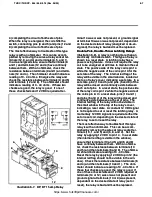
Illus
Illustration 6-6.
tration 6-6. DP
DP, DT 10 amp Relay
, DT 10 amp Relay
Double-Pole, Double-Throw 15 amp Relays
Double-Pole, Double-Throw 15 amp Relays
(Illustration 6-7)
(Illustration 6-7)
..
A relay is nothing more than an
A relay is nothing more than an
electri
electrically contr
cally controlled switc
olled switch.
h. Relays are always
Relays are always
shown on electrical circuits in a de-energized
shown on electrical circuits in a de-energized
state.
state. The positiv
The positive side of the relay coi
e side of the relay coil is pin 14
l is pin 14
whi
while the negativ
le the negative side of the coil is pin 13.
e side of the coil is pin 13. Eith
Either
er
signal, 12 VDC or ground (or both), can be sent to
signal, 12 VDC or ground (or both), can be sent to
the relay coil to energize the relay.
the relay coil to energize the relay.
When the relay is de-energized, the internal
When the relay is de-energized, the internal
switch connects pins (9 and 1) and pins (12 and
switch connects pins (9 and 1) and pins (12 and
https://www.forkliftpdfmanuals.com/

