THDC / THDCP - 954 / 955 / 974 (Rev. 06/03)
THDC / THDCP - 954 / 955 / 974 (Rev. 06/03)
1-32
1-32
Section 2
Section 2
Fuel System
Fuel System
2 1
2 1
THDC / THDCP 954 / 955 / 974 (Rev 06/03)
THDC / THDCP 954 / 955 / 974 (Rev 06/03)
L
LH
H
R
RH
H
FUEL / WATER
FUEL / WATER
SEPARATOR
SEPARATOR
FILTERS
FILTERS
FUEL
FUEL
PUMP
PUMP
FUEL
FUEL
SOLENOID
SOLENOID
FUEL
FUEL
TANK
TANK
FUEL
FUEL
COOLER
COOLER
FUEL FLOW
FUEL FLOW
INDICATES FUEL SUPPLY
INDICATES FUEL SUPPLY
INDICA
INDICATES
TES FUEL
FUEL RECOVER
RECOVERY
Y
SUPPLY
SUPPLY
LINE
LINE
RETURN
RETURN
LINE
LINE
ENGINE
ENGINE
CYLINDER
CYLINDER
HEAD
HEAD
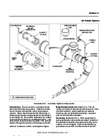
Illust
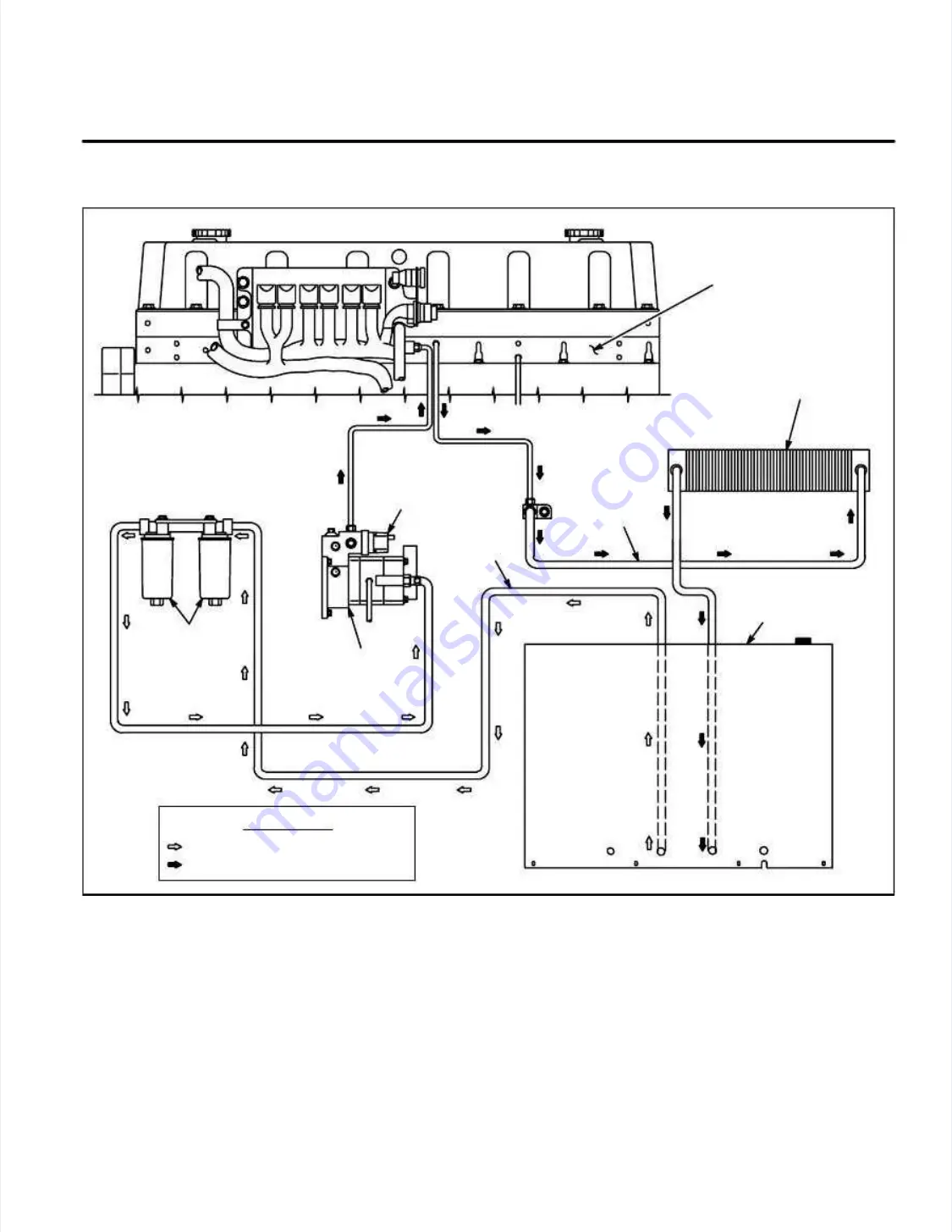
Illustration 2-
ration 2-1.
1. Fuel Sy
Fuel System
stem
Introduction.
Introduction.
Fuel is drawn from the tank through
Fuel is drawn from the tank through
the fuel / water separator filters by the fuel pump.
the fuel / water separator filters by the fuel pump.
From here, the fuel is sent to the fuel injectors.
From here, the fuel is sent to the fuel injectors.
Unused fuel is returned through the fuel cooler
Unused fuel is returned through the fuel cooler
and into the fuel tank.
and into the fuel tank.
Major Components
Major Components
(Illustration 2-1)
(Illustration 2-1)
..
The fuel
The fuel
system consists of a fuel tank, two fuel / water
system consists of a fuel tank, two fuel / water
separator filters, fuel pump, fuel solenoid valve,
separator filters, fuel pump, fuel solenoid valve,
fuel cooler, fuel injectors and fuel lines.
fuel cooler, fuel injectors and fuel lines.
Fuel Solenoid Valve
Fuel Solenoid Valve
(Illustration 2-1)
(Illustration 2-1)
..
The fuel
The fuel
solenoid valve, located on the fuel pump itself,
solenoid valve, located on the fuel pump itself,
controls the on / off flow of fuel to the fuel injec-
controls the on / off flow of fuel to the fuel injec-
tors.
tors. The fuel solenoi
The fuel solenoid valve is norm
d valve is normally cl
ally closed
osed
and requires a 12 VDC signal to energize the coil,
and requires a 12 VDC signal to energize the coil,
shifting the s
shifting the spool to the open state.
pool to the open state. This all
This allows
ows
the fuel to flow to the injector pump.
the fuel to flow to the injector pump.
Adding Fuel
Adding Fuel
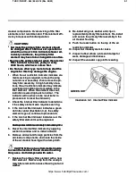
(Illustration 2-3)
(Illustration 2-3)
..
When adding die-
When adding die-
sel fuel to the fuel tank, make sure the fuel strain-
sel fuel to the fuel tank, make sure the fuel strain-
er is in the filler nec
er is in the filler neck and free of debris.
k and free of debris. Addi
Adding
ng
fuel with the strainer removed could lead to debris
fuel with the strainer removed could lead to debris
entering the fuel tank, resulting in poor engine
entering the fuel tank, resulting in poor engine
performance.
performance.
Fuel Cooler
Fuel Cooler
(Illustration 2-1)
(Illustration 2-1)
..
The fuel cooler,
The fuel cooler,
located inside the radiator shroud, is forced-air
located inside the radiator shroud, is forced-air
https://www.forkliftpdfmanuals.com/


