background image


THDC / THDCP - 954 / 955 / 974 (Rev. 06/03)

THDC / THDCP - 954 / 955 / 974 (Rev. 06/03)

1-4

1-4

comes fi

comes first. 

rst.  If steam is not av

If steam is not available, use a sol

ailable, use a sol--

vent to was

vent to wash the engine. 

h the engine.  When cl

When cleanin

eaning the

g the

engine, protect all electrical components, open-

engine, protect all electrical components, open-
ings and wiring from the full force of the cleaner

ings and wiring from the full force of the cleaner
spray nozzle.

spray nozzle.

WARNING:

WARNING:

 When using a steam cleaner,

 When using a steam cleaner,

wear protective clothing and safety glasses or

wear protective clothing and safety glasses or
a face shield. 

a face shield.  Hot steam 

Hot steam will cause serio

will cause serious

us

personal injury.

personal injury.

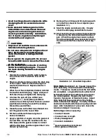
Checking Engine Mounting Bolts.

Checking Engine Mounting Bolts.

  The  engine

  The  engine

mounting bolts should be checked for the

mounting bolts should be checked for the
appropriate torque every 6 months or 1500 hours,

appropriate torque every 6 months or 1500 hours,
whichev

whichever comes fi

er comes first. 

rst.  The torque value of the

The torque value of the

engine mounting bol

engine mounting bolts is 380 ft-l

ts is 380 ft-lbs. 

bs.  Inspect the

Inspect the

rubber mounts for deterioration and age harden-

rubber mounts for deterioration and age harden-
ing. 

ing.  Repl

Replace any broke

ace any broken or 

n or  los

lost bolts and dam-

t bolts and dam-

aged rubber mounts.

aged rubber mounts.

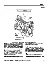
Cummins QSM11-C330 Engine General Infor-

Cummins QSM11-C330 Engine General Infor-

mation

mation

O

Oiil  

l  P

Prre

es

ss

su

urre  

e  ((n

no

orrm

ma

all)  

)  

2

28  

8  -  

-  3

35  

5  p

ps

sii

Oil Capacity

Oil Capacity

(includ

(includes 

es filter change)

filter change)


39.2 

39.2 quarts

quarts

H

Hiig

gh  

h  R

RP

PM

Ms  

s  ((n

no  

o  llo

oa

ad

d)  

)  

2

22

25

50  

0  rrp

pm

m

L

Lo

ow  

w  R

RP

PM

Ms  

s  

7

75

50  

0  rrp

pm

m

 NOTES:

 NOTES:

SS

   Setting  high 

Setting  high rpms 

rpms under  no  load 

under  no  load conditi

conditions  to

ons  to

 2250 

 2250  rpm 

rpm ensures 

ensures  that 

that  the 

the  engine 

engine  will 

will have

have

 2100 

 2100  rpms 

rpms under 

under  a 

a  loaded 

loaded  condition.

condition.

SS

   Some  spec

Some  special  appl

ial  applications 

ications may  us

may  use  engine

e  engine

 speed 

 speed  settings 

settings  that 

that  are 

are  different 

different  from 

from the 

the  stan-

stan-

dards show

dards shown. 

n.  The proper s

The proper settings are 

ettings are perma-

perma-

 nently 

 nently  stamped 

stamped  on 

on  a 

a  metal 

metal  tag 

tag  affixed 

affixed  to 

to  the

the

engine.

engine.

Calibration Of Electronic Accelerator Pedal To

Calibration Of Electronic Accelerator Pedal To
ECM Of Engine.

ECM Of Engine.

 The Cummins QSM11 engine

 The Cummins QSM11 engine

uses an electronic accelerator to control engine

uses an electronic accelerator to control engine
speed. 

speed.  Each time t

Each time the acceler

he accelerator pedal is

ator pedal is

changed, disconnected and the ignition switch is

changed, disconnected and the ignition switch is
turned on, or ECM (Electronic Control Module) is

turned on, or ECM (Electronic Control Module) is
changed out, the accelerator pedal must be cali-

changed out, the accelerator pedal must be cali-
brated to the ECM. 

brated to the ECM.  Calibr

Calibration procedur

ation procedures are as

es are as

follows:

follows:

1. 

1.  Apply t

Apply the park

he parking bra

ing brake, pl

ke, place the sh

ace the shift

ifter in

er in

neutral, and turn the ignition switch to the Igni-

neutral, and turn the ignition switch to the Igni-

tion position (first click).

tion position (first click).

2. 

2.  Cyc

Cycle the acce

le the acceler

lerator peda

ator pedal throu

l through its ful

gh its fulll

range of travel three times.

range of travel three times.

3. 

3.  Tur

Turn the igniti

n the ignition swit

on switch to the Of

ch to the Off positi

f position for

on for

30 seconds.

30 seconds.

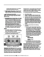
Diagnostic Lights

Diagnostic Lights

 (Illustration 1-5)

 (Illustration 1-5)

..

  The  diagnos-

  The  diagnos-

tic lights, located on the right side of the dash, are

tic lights, located on the right side of the dash, are
used to alert the operator of engine related prob-

used to alert the operator of engine related prob-
lems. 

lems.  At initial power up, all 3 light

At initial power up, all 3 lights will be illum

s will be illumi-

i-

nated for 2 secon

nated for 2 seconds. 

ds.  Afte

After 2 

r 2  sec

seconds, th

onds, the red

e red

light wil

light will turn off. 

l turn off.  After 2.5 seconds

After 2.5 seconds, the yellow

, the yellow

light wi

light will turn off

ll turn off. 

.  After 3 seconds 

After 3 seconds from power up,

from power up,

the blue light will tur

the blue light will turn off. 

n off.  Each light’

Each light’s function is

s function is

listed as 

listed as follows

follows::

1.

1.

   Blue 

Blue Light.

Light.

 This light will begin to flash at

 This light will begin to flash at

approximately 230 hours, indicating routine

approximately 230 hours, indicating routine
maintenance is for

maintenance is forthcomi

thcoming. 

ng.  This light il

This light illumi-

lumi-

nates at approximately 250 hours when rou-

nates at approximately 250 hours when rou-
tine maintenance is re

tine maintenance is required. 

quired.  T

To reset this

o reset this

light, perform the following procedures to reset

light, perform the following procedures to reset

the blue light:

the blue light:

a. 

a.  T

Toggle  the  di

oggle  the  diagnostic 

agnostic swit

switch  (loc

ch  (located

ated

inside the dash on the right side) to the ON

inside the dash on the right side) to the ON
position.

position.

b. 

b.  Tur

Turn  the  ignit

n  the  ignition  key 

ion  key to  its 

to  its accessor

accessory  posi-

y  posi-

tion (first click).

tion (first click).

c. 

c.  All

Allow all th

ow all the diagno

e diagnosti

stic ligh

c lights to com

ts to complet

plete

e

the flash sequences prior to starting proce-

the flash sequences prior to starting proce-
dure 4.

dure 4.

d. 

d.  Ful

Fully depr

ly depress th

ess the accel

e accelerat

erator pedal an

or pedal and

d

hold for more than 3 seconds.

hold for more than 3 seconds.

e. 

e.  Fully 

Fully depress 

depress the  acc

the  accelerator 

elerator pedal  tw

pedal  twice

ice

(each time less than 1 second).

(each time less than 1 second).

f. 

f.  Full

Fully  dep

y  depres

ress  t

s  the  ac

he  accel

celerat

erator  p

or  pedal 

edal and

and

hold for more than 3 seconds.

hold for more than 3 seconds.

 NOTE:

 NOTE:

 Procedures d. through f. must be com-

 Procedures d. through f. must be com-

 pleted 

 pleted  within 

within 30 

30  seconds.

seconds.

g. 

g.  The blue li

The blue light wil

ght will flas

l flash three quic

h three quick flas

k flashes

hes

signifying that the ECM has responded to

signifying that the ECM has responded to
the reset command.

the reset command.

h. 

h.  T

Toggle  the  di

oggle  the  diagnostic 

agnostic switc

switch  to  the  OF

h  to  the  OFF

F

position.

position.

i. 

i.  T

Turn t

urn the ig

he ignit

nition s

ion swit

witch to 

ch to the O

the OFF p

FF posi-

osi-

tion. 

tion.  Allow the ig

Allow the ignition swi

nition switch to remain of

tch to remain off 

for a minimum of 30 seconds before turn-

for a minimum of 30 seconds before turn-

https://www.forkliftpdfmanuals.com/

Summary of Contents for THDC-954

Page 1: ...Maintenance Manual Maintenance Manual THDC THDCP 954 955 974 THDC THDCP 954 955 974 https www forkliftpdfmanuals com...

Page 2: ...AKING SHARP TURNING TURNING HIGH WIND VELOCITY HIGH WIND VELOCITY AND POOR YARD AND POOR YARD CONDITIONS CONDITIONS D D TIL TILT MAST T MAST AND LOAD AND LOAD OUT OUT ONLY ONLY WHEN LOAD IS OVER WHEN...

Page 3: ...n ele er an elevate vated load d load 7 7 T Trans ransport t port the load low an he load low and tilt d tilted back ed back 8 8 Av Avoid su oid sudden s dden stops w tops with a l ith a load oad 9 9...

Page 4: ...https www forkliftpdfmanuals com...

Page 5: ...be excluded after the first six 6 months or one thousand 1000 hours whichever occurs first months or one thousand 1000 hours whichever occurs first 2 2 Normal de Normal deteriorati terioration of appe...

Page 6: ...https www forkliftpdfmanuals com...

Page 7: ...e be anticipated anticipated Do Do not not perform any service if you are unsure perform any service if you are unsure that it can that it can be done be done safely safely Contact your T Contact your...

Page 8: ...n 29 CFR 1910 les found in 29 CFR 1910 178 Appendix A in Safety Chec 178 Appendix A in Safety Check k ANSI B56 1 rules for operati ANSI B56 1 rules for operating a powered industrial tr ng a powered i...

Page 9: ...thing g Failure to follow the safety precautions outlined in Failure to follow the safety precautions outlined in this manual can create a dangerous situation this manual can create a dangerous situa...

Page 10: ...raulic safety devices have been installed on this container handling truck to help protect on this container handling truck to help protect against personal injury and or damage to against personal in...

Page 11: ...advise personnel of proper operati operating proced ng procedures of the lift tr ures of the lift truck uck Do not Do not remove or obscure any warning caution dan remove or obscure any warning cautio...

Page 12: ...tacks of containers or mate rials can cause blind spots for the operator rials can cause blind spots for the operator It is essential for safe operation that the It is essential for safe operation tha...

Page 13: ...h the procedure employees shall comply with the procedure Responsibility Responsibility The responsibility for seeing that The responsibility for seeing that this procedure is followed is binding upon...

Page 14: ...ew or a supervisor with the vidual of a work crew or a supervisor with the knowledge of the crew may lock out tag out knowledge of the crew may lock out tag out equipment for the whole cr equipment fo...

Page 15: ...the operator facing forward looking toward the mast assembly assembly ATT ATTACHMENT ACHMENT Section 29 Section 29 MAST MAST Section 27 Section 27 CAB CAB Section 20 Section 20 STEER AXLE STEER AXLE S...

Page 16: ...1 2 1 2 Rev Rev 11 94 11 94 https www forkliftpdfmanuals com...

Page 17: ...si io on n O Oi il l C Co oo ol le er r 9 9A A T Tr ra an ns sm mi is ss si io on n C Co on nt tr ro ol ls s 9 9C C D Dr ri iv ve e S Sh ha af ft t 1 11 1 S St te ee er r A Ax xl le e 1 13 3 D Dr ri i...

Page 18: ...https www forkliftpdfmanuals com...

Page 19: ...H H Hy yd dr ra au ul li ic c S Sy ys st te em m 2 22 2 C Ca ab b T Ti il lt t S Sy ys st te em m 2 22 2D D Accumulator Accumulator 22E 22E M Ma as st t A As ss se em mb bl ly y 2 27 7 C Co on nt ta a...

Page 20: ...https www forkliftpdfmanuals com...

Page 21: ...il If additi If additional engine infor onal engine information is mation is needed needed refer to the engine operation and maintenance refer to the engine operation and maintenance manual supplied w...

Page 22: ...filter tact the gasket on the new oil filter 6 6 Fil Fill the new fi l the new filter w lter with cl ith clean engi ean engine oil ne oil before before install installation ation 7 7 Apply a li Apply...

Page 23: ...of 140 ft lbs 190 N torque value of 140 ft lbs 190 N m m 4 4 Chec Check the belt t k the belt tensi ension again to m on again to make sur ake sure the e the belt is adjusted to the correct value belt...

Page 24: ...switch to the Igni neutral and turn the ignition switch to the Igni tion position first click tion position first click 2 2 Cyc Cycle the acce le the acceler lerator peda ator pedal throu l through i...

Page 25: ...uter equipped inactive fault codes a laptop computer equipped with Cummins Insite software is required with Cummins Insite software is required To view active fault codes perform the following To view...

Page 26: ...ssu ur re e i is s below the low oil pressure engine protection below the low oil pressure engine protection limit limit Progressive power and speed derate with Progressive power and speed derate wit...

Page 27: ...ted ted 2 22 27 7 Y Ye el ll lo ow w Hi Hig gh h v vo ol lt ta ag ge e d de et te ect cte ed d o on n t th he e E ECM CM v vo ol lt ta ag ge e supply line to some sensors VSEN2 supply supply line to...

Page 28: ...tection for OEM pressure No engine protection for OEM pressure 298 Yellow 298 Yellow Transmission s Transmission s temperature temperature exceeds exceeds 245 245_ _F F Engin Engine wi e will ll shut...

Page 29: ...er derate with increasing time Progressive power derate with increasing time from aler from alert t Engine wil Engine will shut down 30 seconds l shut down 30 seconds after red light starts flashing a...

Page 30: ...ECM No action taken by the ECM 551 Yellow 551 Yellow No No voltage voltage detected detected simultaneously simultaneously on on both both the idle validation off idle and on idle circuits the idle va...

Page 31: ...r restric striction to tion to air c air compres ompres sor is sor is excess excessive ive 2 2 Air Air sys system tem leak leaks s 3 3 Car Carbon buil bon buildup exc dup excessi essive in the ai ve...

Page 32: ...s system tem leak leaks s 2 2 Defecti Defective ve air air governor governor 1 1 Refe Refer to Cor r to Correc rection 2 o tion 2 of Prob f Problem lem 1 of this troubleshooting chart 1 of this troubl...

Page 33: ...ht ighten if en if necessary necessary 5 5 Add or d Add or drai rain engin n engine oil a e oil as req s requir uired ed 6 6 Insp Inspect s ect shroud hroud repa repair or r ir or replac eplace e 7 7...

Page 34: ...ion or response is poor poor 1 1 Elec Electron tronic faul ic fault codes ar t codes are acti e active ve 2 2 Engin Engine operatin e operating at low ambient g at low ambient temperature temperature...

Page 35: ...crank ranking ing rpm rpm Refe Refer r to Problem 26 of this troubleshoot to Problem 26 of this troubleshoot ing chart ing chart 10 10 Iso Isolate and tighten wir late and tighten wire e 11 Contact a...

Page 36: ...chart bleshooting chart 3 3 Refe Refer to Pr r to Problem oblem 10 of th 10 of this tr is trou ou bleshooting chart bleshooting chart 4 4 Insp Inspect an ect and tight d tighten mot en motor mou or mo...

Page 37: ...Facility Repair Facility 19 19 Engin Engine runs roug e runs rough h at idle at idle 1 1 Engine op Engine operating at lo erating at low ambient w ambient temperatures temperatures 2 2 Electroni Elect...

Page 38: ...Contact a Cum Contact a Cummins Author mins Authorized ized Repair Facility Repair Facility 21 21 Engi Engine shuts of ne shuts off f unexpectedly or unexpectedly or dies during decel dies during dece...

Page 39: ...e ive 11 Fuel cutoff valve is closed 11 Fuel cutoff valve is closed 1 1 Re Refer fer to to the the QSM11 Fault Code QSM11 Fault Code Information Information chart in this section chart in this section...

Page 40: ...CB1 i CB1 is defec s defective tive 9 9 Def Defecti ective tr ve truck po uck power s wer soleno olenoid id L1 L1 10 10 Defecti Defective neutral start rel ve neutral start relay K1 ay K1 11 Defectiv...

Page 41: ...s malfunc alfunc tioning tioning 2 2 Engin Engine is r e is runni unning on fum ng on fumes dr es drawn awn into air intake into air intake 1 1 Check Check ignition ignition key s key switch witch cir...

Page 42: ...ary if necessary 4 4 Inspect c Inspect charge air harge air cooler cooler radiator radiator and Freon condens and Freon condenser er Clean fins Clean fins if if necessary necessary 5 5 Cont Contact a...

Page 43: ...do Oil does not m es not meet sp eet specif ecifica ication tions s 6 6 Oil c Oil contam ontaminat inated wit ed with cool h coolant or ant or fuel fuel 7 7 Oil f Oil filt ilter er s ar s are plug e...

Page 44: ...this troubleshooting chart 4 4 Cont Contact a Cu act a Cumm mmins Au ins Author thorize ized d Repair Facility Repair Facility 39 39 Lubr Lubrica icating or ting or transm transmission oil ission oil...

Page 45: ...pair Facility Repair Facility 42 42 Intak Intake e mani manifold fold pressure Boost is pressure Boost is below normal below normal 1 1 Air i Air intak ntake or ex e or exhaus haust leak t leaks s 2 2...

Page 46: ...im mu um m fu fue el l i in nl le et t re res str tri ic cti tio on n D Di irt rty y fu fue el l fi fil lte ter r i in n H Hg g m mm m H Hg g 8 8 2 20 03 3 C Cl le ea an n f fu ue el l f fi il lt te...

Page 47: ...Illust Illustration 1 6 ration 1 6 Cummi Cummins QSM11 C ns QSM11 C330 Engine 330 Engine Electrica Electrical Wiring ANSI Circuit l Wiring ANSI Circuit https www forkliftpdfmanuals com...

Page 48: ...1 27 1 27 THDC THDCP 954 955 974 Rev 06 03 THDC THDCP 954 955 974 Rev 06 03 https www forkliftpdfmanuals com...

Page 49: ...THDC THDCP 954 955 974 Rev 06 03 THDC THDCP 954 955 974 Rev 06 03 1 28 1 28 06B 2106 SHT 02 06B 2106 SHT 02 https www forkliftpdfmanuals com...

Page 50: ...1 29 1 29 THDC THDCP 954 955 974 Rev 06 03 THDC THDCP 954 955 974 Rev 06 03 Hoist Circuit Hoist Circuit https www forkliftpdfmanuals com...

Page 51: ...1 30 1 30 Hoist Circuit Hoist Circuit PLACE THE FOLLOWING ILLUSTRATIONS IN PLACE THE FOLLOWING ILLUSTRATIONS IN FOLDER ENVELOPES FOLDER ENVELOPES Illustration 1 7 CUMMINS QSM11 ECM CIRCUIT Illustrati...

Page 52: ...1 31 1 31 THDC THDCP 954 955 974 Rev 06 03 THDC THDCP 954 955 974 Rev 06 03 Hoist Circuit Hoist Circuit https www forkliftpdfmanuals com...

Page 53: ...l injectors and fuel lines fuel cooler fuel injectors and fuel lines Fuel Solenoid Valve Fuel Solenoid Valve Illustration 2 1 Illustration 2 1 The fuel The fuel solenoid valve located on the fuel pump...

Page 54: ...lint free cloth 5 5 Inst Install the ne all the new threa w thread adapter s d adapter seali ealing ring ng rings on s on the fuel filter head the fuel filter head 6 6 Fill new Fill new filter filters...

Page 55: ...ILLER CAP FILLER CAP FUEL STRAINER FUEL STRAINER FILLER NECK FILLER NECK FUEL TANK FUEL TANK FUEL LEVEL FUEL LEVEL SENDING UNIT SENDING UNIT DRAIN PLUG DRAIN PLUG COVER PLATE COVER PLATE Illustr Illus...

Page 56: ...2 3 2 3 THDC THDCP 954 955 974 Rev 06 03 THDC THDCP 954 955 974 Rev 06 03 https www forkliftpdfmanuals com...

Page 57: ...p to 85 of the dust from the ai of the dust from the air by centri r by centrifugal action fugal action The The dust is then forc dust is then forced out the vacuator ed out the vacuator The air then...

Page 58: ...lter i lter indicator ndicator indicates indicates a green a green dot in its center Illustration 3 2 the safety dot in its center Illustration 3 2 the safety element is good continue to procedure 6 e...

Page 59: ...imary e ry elem lement ent c c Loos Loose pri e primar mary fi y filter lter elem element ent wing nut wing nut 1 1 a a Repl Replace ace elem element ent b b Replace Replace primar primary f y filter...

Page 60: ...3 3 3 3 THDC THDCP 954 955 974 Rev 06 03 THDC THDCP 954 955 974 Rev 06 03 https www forkliftpdfmanuals com...

Page 61: ...carbon monoxide de poisoning include headaches dizzi poisoning include headaches dizzi ness and nau ness and nausea sea The smell o The smell of lift tr f lift truck uck exhaust means carbon monoxide...

Page 62: ...4 1 4 1 THDC THDCP 954 955 974 Rev 06 03 THDC THDCP 954 955 974 Rev 06 03 https www forkliftpdfmanuals com...

Page 63: ...additive concentration level may be The coolant additive concentration level may be tested with a coolant test kit Taylor part number tested with a coolant test kit Taylor part number 1006 175 1006 1...

Page 64: ...tenance manual for the coolant filter ch filter change interval ange interval Perform the foll Perform the following proce owing proce dures to replace the coolant filter dures to replace the coolant...

Page 65: ...pproximately 180 at approximately 180_ _F and fully open when the F and fully open when the coolant temperature coolant temperature reaches approximately reaches approximately 201 201_ _F F General In...

Page 66: ...SION TRANSMISSION OIL COOLER OIL COOLER 7 PSI PRESSURE CAP 7 PSI PRESSURE CAP 15 PSI PRESSURE CAP 15 PSI PRESSURE CAP FUEL FUEL COOLER COOLER Illust Illustration 5 3 ration 5 3 Cooling Compone Cooling...

Page 67: ...EMOVES UNWANTED AIR FROM COOLING CIRCUIT DEAERATION REMOVES UNWANTED AIR FROM COOLING CIRCUIT COOLANT FILTER FLOW COOLANT FILTER FLOW MAKE UP FLOW MAKE UP FLOW 05 2290 05 2290 CUMMINS QSM11 C330 CUMMI...

Page 68: ...5 5 5 5 THDC THDCP 954 955 974 Rev 06 03 THDC THDCP 954 955 974 Rev 06 03 https www forkliftpdfmanuals com...

Page 69: ...any damaged aged parts parts Clean and re Clean and re apply a li apply a light coating of ght coating of grease to the terminals and cable clamps grease to the terminals and cable clamps when necessa...

Page 70: ...provide protection against some of these cir cumstanc cumstances however it es however it is recommended that is recommended that extreme caution be used extreme caution be used Never disconnect the...

Page 71: ...R CB5 CB5 15 15 amp amp GAUGES GAUGES PANEL LIGHT PANEL LIGHT DIAGNOSTIC DIAGNOSTIC LIGHTS POWER LIGHTS POWER BUZZER BUZZER CB24 CB24 15 15 amp amp CB3 CB3 15 15 amp amp CB2 CB2 10 10 amp amp REAR REA...

Page 72: ...AB FANS 15 amp DOME LIGHT CAB FANS CB14 CB14 15 amp AIR SEAT AUTOSHIFT 15 amp AIR SEAT AUTOSHIFT CB15 CB15 15 amp BACK ALARM ENABLE 15 amp BACK ALARM ENABLE RELAY STROBE HORN RELAY RELAY STROBE HORN R...

Page 73: ...mployed in the electrical system and act similar to fuses in the electrical system and act similar to fuses protecting the electrical circuits and valuable com protecting the electrical circuits and v...

Page 74: ...le the negative side of the coil is pin 13 pin 14 while the negative side of the coil is pin 13 Either signal 12 VDC or ground or both can be Either signal 12 VDC or ground or both can be sent to the...

Page 75: ...0 ohms 40 ohms Ener Energiz gize the relay and e the relay and check the resistance between terminals 9 and 5 check the resistance between terminals 9 and 5 and terminal and terminals 12 and 8 s 12 an...

Page 76: ...the top of relay s cover er indicating a set state indicating a set state In a In a set state pins 10 and 5 and pins 6 and 8 of the set state pins 10 and 5 and pins 6 and 8 of the relay will be closed...

Page 77: ...8 mum targeting distance is approximately 3 8 The most effective way to troubleshoot the prox The most effective way to troubleshoot the prox imity sw imity switch is wit itch is with an ohmmeter h a...

Page 78: ...of val e spools of valves ves The The simplest way to prove the solenoid coil good is to simplest way to prove the solenoid coil good is to energize the solenoid and then with a metal energize the sol...

Page 79: ...Inspect the wiring for defects b Inspect the wiring for defects Check all connections for tight Check all connections for tight ness and cleanliness includ ness and cleanliness includ ing the slip co...

Page 80: ...remove the wire from the I termi remove the wire from the I termi nal and rec nal and recheck v heck volta oltage ge If 12 If 12 VDC is now present there is a VDC is now present there is a short betw...

Page 81: ...he S termi nal of the ignition switch for 12 nal of the ignition switch for 12 VDC VDC If not pr If not present re esent remove the move the wire from the S terminal turn the wire from the S terminal...

Page 82: ...3 is assist in determining if the low air switch S13 is defective if a short exists on wire 31 or if a low defective if a short exists on wire 31 or if a low air pressur air pressure problem exists e...

Page 83: ...n when the wip the wiper motor to the Park position when the wip er swit er switch S7 is tur ch S7 is turned off ned off There wil There will be 12 VDC l be 12 VDC present on the green wire when the w...

Page 84: ...e the contacts of the Operator Controlled Mode the contacts of the swit switch are open ch are open With the forw With the forward alarm m ard alarm mode ode key switch S14 turned to the Automatic Pos...

Page 85: ...e seat be ve seat belt sw lt switc itch S18 h S18 1 1 Re Refer fer to to the the Component Trouble Component Trouble shooting shooting found earlier in this sec found earlier in this sec tion tion 2 2...

Page 86: ...ak in brake cooling circuit b Defective pressure relief valve b Defective pressure relief valve in port 3 of the brake manifold in port 3 of the brake manifold valve valve 4 4 Brake Brake coolant cool...

Page 87: ...Park brake sw ake switc itch S1 h S11 is def 1 is defec ec tive tive 3 3 Air p Air pres ressure i sure is bel s below 60 ps ow 60 psi i 1 1 Rel Release ease park parking ing brak brake e 2 2 Replace...

Page 88: ...6 19 6 19 THDC THDCP 954 955 974 Rev 06 03 THDC THDCP 954 955 974 Rev 06 03 https www forkliftpdfmanuals com...

Page 89: ...DC THDCP 954 955 974 Rev 06 03 THDC THDCP 954 955 974 Rev 06 03 6 20 6 20 Illust Illustration 6 1 ration 6 11 1 T Truck Layout Wiring Diagram ruck Layout Wiring Diagram https www forkliftpdfmanuals co...

Page 90: ...6 21 6 21 THDC THDCP 954 955 974 Rev 06 03 THDC THDCP 954 955 974 Rev 06 03 https www forkliftpdfmanuals com...

Page 91: ...THDC THDCP 954 955 974 Rev 06 03 THDC THDCP 954 955 974 Rev 06 03 6 22 6 22 06 23 06 2366 66 SHT SHT 03 03 https www forkliftpdfmanuals com...

Page 92: ...6 23 6 23 THDC THDCP 954 955 974 Rev 06 03 THDC THDCP 954 955 974 Rev 06 03 Hoist Circuit Hoist Circuit https www forkliftpdfmanuals com...

Page 93: ...HDC THDCP 954 955 974 Rev 06 03 THDC THDCP 954 955 974 Rev 06 03 6 24 6 24 Illust Illustration 6 12 ration 6 12 T Truck Contro ruck Control ANSI Diagram l ANSI Diagram https www forkliftpdfmanuals com...

Page 94: ...6 25 6 25 THDC THDCP 954 955 974 Rev 06 03 THDC THDCP 954 955 974 Rev 06 03 https www forkliftpdfmanuals com...

Page 95: ...THDC THDCP 954 955 974 Rev 06 03 THDC THDCP 954 955 974 Rev 06 03 6 26 6 26 https www forkliftpdfmanuals com...

Page 96: ...6 27 6 27 THDC THDCP 954 955 974 Rev 06 03 THDC THDCP 954 955 974 Rev 06 03 06 2366 SHT 10 06 2366 SHT 10 Hoist Circuit Hoist Circuit https www forkliftpdfmanuals com...

Page 97: ...955 974 Rev 06 03 THDC THDCP 954 955 974 Rev 06 03 6 28 6 28 06 2366 SHT 06 06 2366 SHT 06 Illust Illustration 6 13 ration 6 13 Main Cont Main Control Junctio rol Junction Box n Box https www forklift...

Page 98: ...9 THDC THDCP 954 955 974 Rev 06 03 THDC THDCP 954 955 974 Rev 06 03 I 1 29 0640 I 1 29 0640 Illust Illustration 6 ration 6 14 14 Cab Rear Pan Cab Rear Panel Harness el Harness https www forkliftpdfman...

Page 99: ...HE FOLLOWING ILLUSTRATIONS IN PLACE THE FOLLOWING ILLUSTRATIONS IN FOLDER ENVELOPES FOLDER ENVELOPES Illustration 6 15 06 2366 SHT 10 Truck Control ANSI Illustration 6 15 06 2366 SHT 10 Truck Control...

Page 100: ...6 31 6 31 THDC THDCP 954 955 974 Rev 06 03 THDC THDCP 954 955 974 Rev 06 03 6 6 L L A A u u x x i i l l i i a a r r y y L L i i g g h h t t i i n n g g https www forkliftpdfmanuals com...

Reviews: