background image

12

MASTER Series

OVERALL DIMENSIONS 

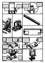
The main overall dimensions of the sliding gate are indicated in fig. 

1, 2 and 3; the base plate dimensions are indicated in fig. 8, while 

the dimensions of the adjustable base plate are indicated in fig. 28.

PRELIMINARY OPERATIONS 

Before starting any type of operation, carefully read the instruction 

present in this manual.

Before  starting  installation,  make  sure  that  all  parts  are  present 

(fig. 4), wear suitable work clothing and accessories and do not 

handle live electrical parts.

INSTALLATION MEASUREMENTS

The measurements indicated in fig. 6 and 7 for the excavation and 

those in fig. 11 for the positioning of the base plate, must be re

-

spected for the correct installation of the gearmotor. 

PRE-INSTALLATION CHECKS 

Use on gates with a gradient or slope is NOT allowed.

Before installation, check that:

-   the wheels of the gate have been fitted so that the gate itself is 

stable, and that they are in good condition and 

  working correctly;

-   the track is free, straight and clean along its entire length and 

has the stops at each end;

-   the upper guide is inline with the track, and is greased and al

-

lows the leaf a play of approx. 1 mm;

-   check that the floor stops are present.

LOCATION

If fixing directly to a concrete surface, choose a position equivalent 

of the area outlined in fig. 6, or as in fig. 7 if an excavation has to 

be made. 

BASE PREPARATION 

Dig a sufficiently wide foundation that is at least 15 cm deep. Intro

-

duce a protective sheathing for the cables. 

FIXING OF THE BASE PLATE 

Note:  the  foundation  counterplate  is  positioned  correctly 

when the arrows on it are pointing in the following directions: 

one towards the gate and the other to the left (1 fig. 12).

Once the foundations are ready, prepare the base plate by insert

-

ing the threaded ties into their holes, securing them on the lower 

face with the 4 narrow nuts and with the 4 locking nuts on the upper 

face (fig. 9). 

Note: the threaded section must be protruding by 

no more than 40 mm in order to secure the gearmotor 

(fig. 10). 

Cover with concrete, making sure that the ties are well imbedded; 

the base plate must be perfectly level and 1 or 2 cm (fig. 11) from 

floor level and approx. 50 mm from the gate (fig. 7).

Note: The gearmotor can also be fitted without the base plate, 

using 4 foundation bolts on a level concrete surface making 

sure that the measurements indicated in fig. 6 are respected. 

Optionally, a height adjustable base plate can be used. In this case 

the fixed ties must be welded to the track and after locked with 4 

expansion bold M12x120 (see fig. 29). The adjustable base plate 

is then secured as indicated in fig. 30.

In this way the gearmotor can be adapted to an already existing 

system; the measurements indicated in fig. 29 must be respected.

SECURING OF THE GEARMOTOR 

Remove the 4 locking nuts from the threaded section of the ties, 

position the gearmotor as illustrated in fig. 13, then secure it us

-

ing the washers and previously mentioned nuts (fig. 14). Pass the 

cables through the hole of the base plate.

Note: a hole has been arranged on the alumium base (fig. 13), 

under  the  transformer  housing,  to  drain  possible  water  de-

posit.

The same operations are also use for the adjustable base plate as 

indicated in fig. 31 and 32.

SECURING OF THE RACK 

Having previously drilled the leaf, secure the rack with the 6.3 mm 

diameter self-tapping screws, see fig. 16.

It is extremely important that the installation measurements 

and the distance between the teeth of the gear and the teeth 

of the rack are respected, as indicated in fig. 18, 19 and 20. 

Note: the rack should run on the gearmotor gear for the entire 

width of its teeth (fig. 24).

There are two available types of rack: the standard enbloc type 

and the sectional type of which each single piece measures 50 cm 

in length fig. 27.

SECURING AND ADJUSTMENT OF THE LIMIT SWITCH 

PADS

Position each pad close to the end of the rack as in fig. 17. Manu

-

ally  manoeuvring  the  leaf,  position  the  pads  so  that  they  make 

slight contact with the microswitch lever just before the interven

-

tion of the mechanical stops at the end of the track, and tighten 

the screws.

The manufacturer advises that a distance between a minimum 

of  15  mm  and  a  maximum  of  18  mm  should  be  maintained 

between the gearmotor casing and the limit switch pads fitted 

on  the  rack  in  order  for  the  automation  system  to  function 

correctly (fig. 23).

The  contact  point  of  the  limit  switch  pads  with  the  spring 

should also be lubricated with a little oil in order to help slid-

ing and prevent the spring from being compressed.

Note: for complete safety, the mechanical stops with rubber 

cap (floor stops) must be fitted, as shown in fig 5.

A single factor or combination of factors (thermal ex-

pansion, climate, frequency of use, etc.) may result in 

the position the gate stops in changing over the course 

of the day, both when opening and when closing. Con-

sequently,  we  cannot  guarantee  that  the  gate  will  al-

ways stop in the same position.

MAGNETIC LIMIT SWITCHES (MASTER20QM)

During  movement,  the  gate  mounting  the  magnets  fitted  on  the 

rack approaches the sensor installed on the gearmotor, and acti

-

vates this sensor, consequently stopping closure.

The magnets must be installed at a distance from the closing edge 

(X, fig. 17B) taking gate inertia into account. We recommend test

-

ing the magnets on the rack before fixing them permanently (the 

magnets remain firmly in place) in order to find the correct position 

for optimal operation.

The magnet with North polarity (black) is used as an opening limit 

switch (OLS), and the magnet with South polarity (red) is used as 

a closing limit switch (CLS).

Note:  to  activate  correctly  the  magnetic  sensor,  dis-

tances as shown in picture 17/B must be respected

IMPORTANT: It is necessary to activate the brake func-

tion (see controller’s manual, “DIP Switches” section) 

when magnetic limit switches are installed.

TYPE OF SYSTEM (fig. 5)

1

   Gearmotor 

2

   Photocell column 

3

   Flashing light with antenna

4

   key operated selector switch 

5

   Safety photocell 

6

   Sensitive edge 

7

   Floor stop

8

   Post for control panel

9

   Control panel complete with casing

ENGLISH

Summary of Contents for MASTER

Page 1: ...ancelli scorrevoli ad uso industriale Sliding Gate Operator Industrial Schiebetorantrieb für Gewerbe und Industrie Automatisme pour Portails Coulissants Usage Industriel Accionador para Puertas Correderas Uso Industrial Via Enrico Fermi 43 36066 Sandrigo VI Italia Tel 39 0444 750190 Fax 39 0444 750376 info tauitalia com www tauitalia com IT Istruzioni originali D_MNL0MASTER 16 12 2014 Rev 27 ...

Page 2: ...book will be corrected in the next edition When opening the packing please check that the product is intact Please recycle materials in compliance with current regulations This product may only be installed by a qualified fitter The manufacturer declines all liability for damage to property and or personal injury deriving from the incorrect installation of the system or its non compliance with cur...

Page 3: ...breaker with multi pole switch is recommended 12 Verificare che a monte dell impianto vi sia un interruttore differenziale con soglia da 0 03 A 13 Verificare che l impianto di terra sia realizzato a regola d ar te e collegarvi le parti metalliche della chiusura 14 I dispositivi di sicurezza norma EN 12978 permettono di proteggere eventuali aree di pericolo da Rischi meccanici di movimento come ad ...

Page 4: ...érieur à 3 mm Il est conseillé d utiliser un interrup teur magnétothermique de 6A avec interruption omnipolaire 12 Prüfen ob hinter der Anlage ein Differenzialschalter mit max 0 03 A vorliegt 13 Prüfen ob die Erdung fachgerecht ausgeführt wurde und die Metallteile des Toröffners daran anschließen 14 Die Sicherheitsvorrichtungen Norm EN 12978 ermög lichen den Schutz eventueller Gefahrenbereiche vor...

Page 5: ...térmico de 6A con inte rrupción omnipolar 12 Compruebe que la parte inicial de la instalación disponga de un interruptor diferencial con un umbral de 0 03 A 13 Compruebe que la instalación de tierra esté realizada con todas las de la ley y conecte en ella las partes metálicas del cierre 14 Los dispositivos de seguridad norma EN 12978 permiten proteger eventuales áreas de peligro de Riesgos mecá ni...

Page 6: ... incorporada y final de recorridos magnéticos MASTER20T Motoriduttore per cancelli fino a 2000 kg motore 400V trifase senza quadro elettrico Gearmotor for gates up to 2000 Kg 400V three phase motor without a control unit Getriebemotor für Tore bis 2000 Kg 400V dreiphasig Motor mit eingebauter Steuer zentrale Motoréducteur pour portails jusqu à 2000 Kg moteur 400V tri phasé sans centrale Motorreduc...

Page 7: ...de réduction Relación de reducción 1 30 Intervento termoprotezione Thermal pro tection trips at Eingreifen des Wärmes chutzes Intervention protection thermique Activatión termoprotección 160 C 150 C Peso max cancello Max gate weight Torgewicht max Poids max portail Peso máximo de la cancela 1200 Kg 1800 Kg 1500 Kg 1000 Kg 2000 Kg Modulo pignone Pinion module Ritzel modul Module pignon Mòdulo piñón...

Page 8: ...uttore come in fig 13 quindi bloccarlo utiliz zando le rondelle e i già citati dadi fig 14 Passare tutti i cavi at traverso i fori ricavati sulla base della contropiastra di fondazione Nota sulla base in alluminio nella sede di alloggiamento del trasformatore è stato ricavato un foro fig 13 per lo scolo di un eventuale deposito d acqua Per la contropiastra regolabile le operazioni sono le medesime...

Page 9: ...sere cablata in serie al comune morsetto 19 della scheda D703M dei finecorsa INSTALLAZIONE BATTERIA 12V Se si vuole dotare il proprio motoriduttore MASTER12Q 18QR 15QRF R di 1 batteria per garantire il funzionamento in assenza di corrente togliere il carter e inserirla nella apposita sede quindi collegare i cavi di alimentazione alle linguette Nota con l utilizzo in batteria le prestazioni per il ...

Page 10: ...norme vigenti Nel caso di demolizione dell automazione non esistono particolari pericoli o rischi derivanti dall automazione stessa È opportuno in caso di recupero dei materiali che siano separati per tipologia parti elettriche rame alluminio plastica etc SMANTELLAMENTO Nel caso l automazione venga smontata per essere poi rimontata in altro sito è necessario togliere l alimentazione e scollegare t...

Page 11: ...ai sensi della Direttiva Macchine 2006 42 CE Dichiara inoltre che questo prodotto è conforme ai requisiti essenziali di sicurezza delle seguenti ulteriori direttive CEE 2006 95 CE Direttiva Bassa Tensione 2004 108 CE Direttiva Compatibilità Elettromagnetica ed ove richiesto alla Direttiva 1999 5 CE Apparecchiature Radio e apparecchiature terminali di telecomunicazione Dichiara inoltre che non è co...

Page 12: ...sly mentioned nuts fig 14 Pass the cables through the hole of the base plate Note a hole has been arranged on the alumium base fig 13 under the transformer housing to drain possible water de posit The same operations are also use for the adjustable base plate as indicated in fig 31 and 32 SECURING OF THE RACK Having previously drilled the leaf secure the rack with the 6 3 mm diameter self tapping ...

Page 13: ...TERY INSTALLATION If one wishes to fit a battery to the MASTER12Q 18QR 15QRF R gearmotor in order to guarantee power in the event of blackout remove the casing and fit the battery into its location then connect the power supply cables to the tongues Note when using in battery the performance of the MASTER R 24v DC is the same as the MASTER12Q with the same speed both opening and closing MANUAL REL...

Page 14: ...e current laws and regulations No dangers or risks are present in the event of scrapping of the automation system If materials are to be recycled they should ideally be divided based on their type electrical parts copper aluminium plastic etc DISMANTLING In the event that the automation system needs to be dismantled and reassembled in another location it is necessary to turn off the power supply a...

Page 15: ...figura Evitate qualsiasi intervento personale e chiamate il vostro installatore una volta sbloccato l impianto funzionerà manualmente come prima dell installazione Manutenzione per durare nel tempo e funzionare in completa sicurezza come qualsiasi altro macchinario l impianto necessita di una periodica manutenzione Stabilite insieme al vostro installatore i tempi di tale manutenzione Tau consiglia...

Page 16: ...near the system and keep the remote control device out of their reach Faults If you notice any abnormal behaviour disconnect the system from the power supply immediately and perform the manual release operation see figure Do not attempt to repair the door but call in your fitter the system will operate manually as it did before installation Maintenance to ensure long life and totally safe operatio...

Page 17: ...tromversorgung zur Automatisierung ab und entriegeln Sie von Hand siehe Abbildung Vermeiden Sie jeden persönlichen Eingriff und rufen Sie Ihren Installateur nach dem Entriegeln wird die Anlage von Hand funktionieren wie vor der Installation Wartung um zu dauern und ganz sicher zu funktionieren bedarf die Anlage wie jede andere Maschine einer periodischen Wartung Legen Sie die Wartungszeiten zusamm...

Page 18: ...e sur la figure Évitez toute intervention personnelle et contactez votre installateur une fois débloquée l installation fonctionnera manuellement comme avant l automatisation Maintenance pour durer dans le temps et fonctionner en toute sécurité comme toute autre machine l installation a besoin d une maintenance périodique Établissez avec votre installateur un plan de maintenance Tau conseille une ...

Page 19: ...ig 1 Fig 2 Fig 3 Fig 4 Fig 5 TX RX TX RX DISEGNI DRAWINGS ZEICHNEN PROJETS DIBUJOS 230 Vac 400 Vac MASTER12Q MASTER15QRF MASTER18QR MASTER20QR MASTER20QM MASTER20T MASTER Series Disegni Drawings Zeichnen Projets Dibujos ...

Page 20: ... GAINES FUNDA SCAVO EXCAVATION GRABEN CREUSEMENT EXCAVACION SCAVO EXCAVATION GRABEN CREUSEMENT EXCAVACION CONTROPIASTRA COUNTERPLATE FUNDAMENTGE GENPLATTE CONTRE PLAQUE CONTRAPLACA 195 100 100 60 95 64 Ø10 2 R20 31 45 210 70 55 60 390 36 159 159 36 60 195 Fig 12 CAVI WIRES KABELS CABLES CABLES GUAINA SHEAT HULLE GAINES FUNDA CANCELLO GATE TOR PORTAIL VERJA 1 MASTER Series Disegni Drawings Zeichnen...

Page 21: ...SCREW SCHRAUBE VIS TORNILLO PATTINO LIMIT ENDGLEITBOCKE PATIN PATINO INGRANAGGIO GEAR ZAHNRAD ENGRENAGE ENGRANAJE CREMAGLIERA RACK ZAHNSTANGE CREMAILLERE CREMALLERA CANCELLO GATE TOR PORTAIL VERJA PATTINO LIMIT ENDGLEITBOCKE PATIN PATINO CREMAGLIERA RACK ZAHNSTANGE CREMAILLERE CREMALLERA MASTER Series Disegni Drawings Zeichnen Projets Dibujos X X 2 mm CREMAGLIERA RACK ZAHNSTANGE CREMAILLERE CREMAL...

Page 22: ... FUNDAMENTGE GENPLATTE CONTRE PLAQUE CONTRAPLACA VITE SCREW SCHRAUBE VIS TORNILLO VITE SCREW SCHRAUBE VIS TORNILLO A 378 mm 10 15 mm Fig 29 SALDATURA WELDING SCHWEISSUNG SOUDURE SOLDADURA ROTAIA RAIL SCHIENE ORNIERE CARRIL SCAVO EXCAVATION GRABEN CREUSEMENT EXCAVACION ZANCA BRACKET BUGEL PATTE GRAPA TASSELLO EXPANSION BOLD SPREIZDUBELN VIS TAPONEE TORNILLO TALADRADORE Fig 31 VITE SCREW SCHRAUBE VI...

Page 23: ...queo manual como muestra la figura No realice ninguna reparación y llame a su instalador una vez desbloqueada la instalación funcionará manualmente como antes de montar la automatización Mantenimiento para garantizar una larga vida útil y para un funcionamiento seguro la instalación al igual que cualquier otra maquinaria requiere un mantenimiento periódico Establezca con su instalador las frecuenc...

Page 24: ...ty circuit breaker Setting and correct operation of electronic clutch Connections and operation of safety devices Anschluss und Funktionstüchtigkeit des Differentialschalters Einstellung und Funktionstüchtigkeit der elktronischen Kupplung Anschlüss und Funktionstüchtigkeit der Sicherheitsvorrichtungen Connexion et efficacité de l interrupteur différentiel Etalonnage et fonctionnement correct de l ...

Page 25: ...ali finecorsa Connection and efficiency of earth socket Operation of manual release device Operation of limit switches if any Anschlüss und Funktionstüchtigkeit der Erdung Funktionstüchtigkeit der manuellen Freigabevorrichtung Funktionstüchtigkeit der eventuellen endschalter Connexion et efficacité de la prise de terre Fonctionnement du dispositif de déblocage manuel Fonctionnement des fins de cou...

Page 26: ...Connections and operation of accessories Gearmotor fixing condition Gate general conditions Fitter s signature User s signature Anschlüss und Funktionstüchtigkeit der Zubehörs Befestigung des Getriebes Allgemeiner Zustand des Tors Unterschrift des Wartungsmannes Unterschrift des Benutzers Connexion et fonctionnement des accessoires Fixatuion du motoréducteur Conditions générales du portail Signatu...

Page 27: ...ctive 2006 42 EC Also declares that this product complies with the essential safety requirements of the following EEC directives 2006 95 EC Low Voltage Directive 2004 108 EC Electromagnetic Compatibility Directive and where required with the Directive 1999 5 EC Radio equipment and telecommunications terminal equipment Also declares that it is not permitted to start up the machine until the machine...

Page 28: ...ern blo ckieren Abb 14 Alle Kabel durch die Bohrungen in der Basis der Fundamentgegenplatte führen BITTE BEMERKEN Durch ein Loch am Alu Boden neben dem Transformator fließt das Wasser ab Abbildung 13 Für die verstellbare Gegenplatte sind dieselben Vorgänge auszu führen wie auf den Abb 31 und 32 angegeben BEFESTIGUNG DER ZAHNSTANGE Nachdem der Torflügel gelocht ist wird die Zahnstange mit selbst sc...

Page 29: ...ie für den Betrieb auch bei Stromausfall ausstatten will das Gehäuse entfernen die Batterie in ihren Sitz einstecken und die Versorgungskabel an den Laschen anschließen Anm Bei Benutzung der Batterie sind die Leistungen für den MASTER R 24V DC diejenigen des MASTER12Q mit der glei chen Geschwindigkeit beim Öffnen und Schließen MANUELLE ENTRIEGELUNG Bei Netzstromausfall den Schlossdeckel heben den ...

Page 30: ...e die recycled werden sollen müssen nach Typik ge trennt werden elektrische Teile Kupfer Aluminium Plastik usw DEMONTAGE Wie folgt vorgehen um die Automatisierung für eine zukünftige Benutzung an einem anderen Ort zu demontieren die Versorgung abschalten und die gesamte elektrische Anlage abtrennen den Getriebemotor von der Befestigungsbasis entfernen alle Anlagenteile demontieren Teile die nicht ...

Page 31: ...Maschine darstellt Außerdem erklärt er dass dieses Produkt den grundsätzlichen Sicherheitseigenschaften der folgenden Richtlinien EWG entspricht 2006 95 EG Niederspannungsrichtlinie 2004 108 EG Richtlinie für elektromagnetische Kompatibilität Und wo gefordert der Richtlinie 1999 5 EG Funkgeräte und Fernmitteilungsendeinrichtungen Außerdem wird erklärt dass es nicht zugelassen ist die Vorrichtung i...

Page 32: ...es rondelles et les 4 écrous fig 14 Faire passer tous les câbles à travers les trous pratiqués sur la base de la contre plaque de fondation Note sur l emplacement du transformateur qui se trouve sur le socle en aluminium nous avons réalisé un trou fig 13 pour permettre l écoulement de l éventuel stockage d eau Pour la contre plaque réglable les opérations sont les mêmes comme indiqué sur les fig 3...

Page 33: ...nnement en cas de coupure de courant il faut enlever le carter et placer la batterie dans le logement prévu à cet effet puis brancher les câbles d ali mentation aux languettes Remarque avec l utilisation en batterie les prestations pour le MASTER R 24V DC sont les mêmes que le MASTER12Q avec la même vitesse en ouverture comme en fermeture DÉBLOCAGE MANUEL En cas de coupure de courant enlever le ca...

Page 34: ...ssaire en cas de récupération des matériaux de les séparer par catégorie parties électriques cuivre aluminium plastique etc DÉMANTÈLEMENT Si l automatisme est démonté pour être ensuite remonté dans un autre lieu il faut couper l alimentation et débrancher toute l installation élec trique retirer le motoréducteur de sa base d ancrage démonter tous les composants de l installation si certains compos...

Page 35: ...Directive Machines 2006 42 CE Déclare d autre part que ce produit est conforme aux exigences essentielles de sécurité des directives CEE suivantes 2006 95 CE Directive Basse Tension 2004 108 CE Directive Compatibilité Électromagnétique et si requis à la Directive 1999 5 CE Équipements hertziens et équipements terminaux de télécommunication Le Fabricant déclare également qu il n est pas permis de m...

Page 36: ...las arandelas y las ya citadas tuercas fig 14 Pase todos los cables a través de los orificios efectuados en la base de la contraplaca de cimentación Nota en la base en Aluminio cerca del transformador un agujero de drenaje Fig 13 permite evacuar un ventual de posito de agua Para la contraplaca regulable las operaciones son las mismas tal como se indica en las figs 31 y 32 FIJACIÓN DE LA CREMALLERA...

Page 37: ...os fines de carrera INSTALACIÓN BATERÍA 12V Si quiere equipar su propio motorreductor MASTER12Q 18QR 15QRF con una batería para garantizar el funcionamiento cuando no haya corriente quite el cárter y colóquela en la sede correspon diente luego conecte los cables de alimentación a las lengüetas Nota con el uso en batería el rendimiento para el MASTER R 24V DC son las mismas que el MASTER12Q con la ...

Page 38: ...or males de uso es constante y no supera los 70 dB DESGUACE La eliminación de los materiales se efectúa respetando las normas vigentes En caso de desguace de la automatización no existen peligros o riesgos particulares derivantes de la propia automatización Es oportuno en caso de recuperación de los materiales que se separen por tipología partes eléctricas cobre aluminio plásti co etc DESMANTELAMI...

Page 39: ...iva Máquinas 2006 42 CE Declara también que este producto cumple con los requisitos esenciales de seguridad de las siguientes ulteriores directivas CEE 2006 95 CE Directiva Baja Tensión 2004 108 CE Directiva Compatibilidad Electromagnética y donde es necesario con los de la Directiva 1999 5 CE Equipos radioeléctricos y equipos terminales de telecomunicación Declara además que no está permitido pon...

Page 40: ...a corrispondere il Diritto fisso di chiamata per spese di trasferimento a domicilio più manodopera La garanzia decade nei seguenti casi Qualora il guasto sia determinato da un impianto non eseguito secondo le istruzioni fornite dall azienda all interno di ogni confe zione Qualora non siano stati impiegati tutti componenti originali TAU per l installazione dell automatismo Qualora i danni siano cau...

Reviews: