background image

27

Installation Guide: 1200-7000 Series Routers

TiOS version 8.0

Tasman 6300

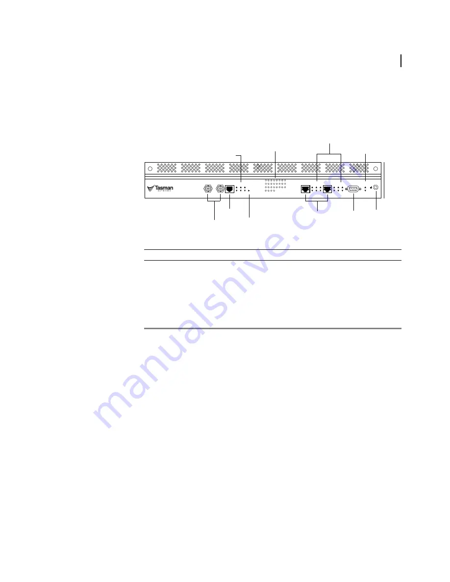
The front panel on these systems provides connections for one CT3 port, one monitor port, two 
10/100 Base-T Ethernet ports, and one console port.

Figure 13  6300 System Front Panel

Table 16   6300 System Front-Panel Connectors 

Connector

Description

CT3 Port

Two BNC connectors 

Monitor Port

One RJ-48C connector

Ethernet Ports (2)

One RJ-45 connector per port

Console Port

DB-9 female connector

Use this port to set up a connection between a VT-100 (or equivalent) terminal (or 
modem) and the 6300 system.

ESD Ground

Banana plug connector 

6300

Link Status

Ethernet 0

Ethernet 1

Console

Unit

1

2

3

4

5

6

7

8

9

10

11

12

13

14

15

16

17

18

19

20

21

22

23

24

25

26

27

28

ESD Gnd

Dup

HS

Link

Col

RX

TX

Power

Summary

Dup

HS

Link

Col

RX

TX

Channelized T3

WAN

DS3

Frame

Yellow

Signal

AIS

Error

Test

Mon.

TX

RX

Status

CT3 Port

 Monitor Port

10/100 Base-T 
Ethernet Ports

Console 
Port

ESD
Ground

CT3 Status LEDs

WAN Status LED

T1 Status LEDs

LAN Status LEDs

Summary
and Power
LEDs

Summary of Contents for 1200 Series

Page 1: ...TiOS version 8 0 July2004 Installation Guide 1200 1400 6200 7000 Series Routers ...

Page 2: ...difies the CFG file Full responsibility for any performance issues resulting from modifications made to the CFG file by the user is assumed by the user Hardware Notice The Lithium battery in this product is part of a non volatile memory device and will retain data for 10 years in the absence of power Tasman Networks does not consider the lithium battery in this unit a field replaceable or servicea...

Page 3: ...0 Series 15 Tasman 1200 15 Tasman 1200E 16 Tasman 1400 17 Tasman 1400E 18 Tasman 1450 19 Tasman 1450E 20 Dial Out Port 20 Back Panel Components 21 4000 Series Systems 22 Tasman 4100 22 Tasman 4102 23 Back Panel Components 24 6000 Series Systems 25 Tasman 6200 25 Tasman 6200E 26 Tasman 6300 27 Tasman 6302 28 Back Panel Components 29 7000 Series Systems 30 Tasman 7030 30 Back Panel Components 31 3 I...

Page 4: ...nterface 46 V 35 Interface 47 Operator Interface 48 Local Access 48 Remote Access 48 Telnet 49 Console Messages 49 Connecting a Modem 50 Hayes Compatible Modem Configuration 51 4 CONFIGURATION Applying Power 53 Logging In 54 Command Tips 54 Configuration Tips 55 HSSI and V 35 Interface 55 Ethernet 55 Changing Login Parameters 56 Password 56 Administrator Account 56 System Host Name 56 Date and Tim...

Page 5: ...ptoms 88 HSSI 91 V 35 92 A SPECIFICATIONS Environment and Power 94 Interface 95 Cable Pinouts 98 MIBs 104 B LED STATES C MAINTENANCE AC Fuse 113 Servicing the Cooling System 115 Fan Filter 115 Replacing Filters 115 Fans 116 D ACCESSORIES Accessories 119 E COMPLIANCE AND STANDARDS Compliance 121 FCC Conformance 122 FCC Part 15 122 FCC Part 68 122 Incidence of Harm 123 Rights of the Telephone Compan...

Page 6: ... Series Routers TiOS version 8 0 Technical Support 131 Procedures 131 Exclusions 131 Non Tasman Networks Products 131 Disclaimer of Warranty 131 Limitation of Liability 132 Equipment Malfunction 132 Contacting Tasman Networks 132 ...

Page 7: ...ront Panel 30 17 7000 Series System Back Panel 31 18 Chassis Air Flow 34 19 Attaching Mounting Brackets 39 20 Rackmounting the System 39 21 DC Power Terminal Block Connections 40 22 Connecting the AC Power Cord 41 23 Preparing Alarm DC Power and Ground Wires 43 24 System Alarm Connections 43 25 Connecting the LAN Cable 44 26 Connecting T1 WAN Cables 45 27 Connecting Channelized T3 WAN Cables 45 28...

Page 8: ......

Page 9: ...6 6300 System Front Panel Connectors 27 17 6302 System Front Panel connectors 28 18 6000 Series System Back Panel Components 29 19 7030 System Front Panel Connectors 30 20 7000 Series Systems Back Panel Components 31 21 Empty Vertical Space Requirement 38 22 DB 25 to DB 9 Pinout 50 23 Generic Hayes Modem Commands 51 24 Ethernet Interface Default Configuration 59 25 IP Default Configuration 59 26 C...

Page 10: ...k Cable RJ 48C to Twinax 99 52 Pinouts E1 Network Cable RJ 48C to BNC 99 53 Pinouts Tasman Console to Null Modem Cable DB 9 to DB 9 100 54 Pinouts Tasman Console to Null Modem Cable DB 25 to DB 9 100 55 Pinouts HSSI Connector DTE 100 56 Pinouts HSSI Connector DCE 101 57 Pinouts V 35 Connector DTE 102 58 Pinouts V 35 Connector DCE 103 59 Standard MIBS 104 60 Tasman Enterprise MIBs 105 61 LEDs Syste...

Page 11: ...stallation and administration of networking equipment in Telco and service provider environments Knowledge of Telecom technologies and standards T1 DS3 HSSI V 35 and Ethernet technologies is assumed Instructions are provided in this guide for installing Tasman systems and configuring basic system parameters Procedures are also provided for tasks that can be accomplished from the external chassis s...

Page 12: ...s powering on the system initial configuration logging in factory defaults and changing the default password 5 Troubleshooting provides information about network indicators tests and general troubleshooting tips A summary of common problems and solutions is also included Table 2 Guide Organization Appendices Appendix Description A Specifications lists the electrical physical and networking charact...

Page 13: ...n of Tasman systems ESD ESD notices provide information about how to avoid discharge of static electricity and subsequent damage to Tasman systems CAUTION Caution notices provide information about how to avoid possible service disruption or damage to Tasman systems WARNING Warning notices provide information about how to avoid personal injury when working with Tasman systems Table 3 Text Conventio...

Page 14: ...d to these products Release Notes Printed release notes provide the latest information If release notes are provided with your product follow the instructions contained within them instead of those provided in other documentation Quick Start Guide 1200 7000 Series Routers This printed guide is designed for advanced users It provides a brief overview of the installation and initial configuration pr...

Page 15: ...l provides connections for one monitor port four T1 ports two 10 100 Base T Ethernet ports and one console port Figure 1 1200 System Front Panel Table 4 1200 System Front Panel Connectors Connector Description Monitor Port One RJ 48C connector T1 Ports Four RJ 48C connectors Ethernet Ports 2 One RJ 45 connector per port Console Port DB 9 female connector Use this port to set up a connection betwee...

Page 16: ...r per port Console Port DB 9 female connector Use this port to set up a connection between a VT 100 or equivalent terminal or modem and the 1400E system ESD Ground Banana plug connector 1200 Link Status Ethernet 0 Ethernet 1 Console Unit 1 2 3 4 Status Mon 1 2 3 4 Dup HS Link Col RX TX Power Summary Dup HS Link Col RX TX Quad T1 WAN ESD Gnd 1200E Link Status Ethernet 0 Ethernet 1 Console Unit 1 2 ...

Page 17: ...RJ 48C connectors Ethernet Ports 2 One RJ 45 connector per port Console Port DB 9 female connector Use this port to set up a connection between a VT 100 or equivalent terminal or modem and the 1400 system ESD Ground Banana plug connector 1400 Link Status Ethernet 0 Ethernet 1 Console Unit 1 2 3 4 5 6 7 8 Status Mon 5 6 7 8 1 2 3 4 Dup HS Link Col RX TX Power Summary Dup HS Link Col RX TX Octal T1 ...

Page 18: ...ector E1 Ports Eight RJ 48C connectors Ethernet Ports 2 One RJ 45 connector per port Console Port DB 9 female connector Use this port to set up a connection between a VT 100 or equivalent terminal or modem and the 1400E system ESD Ground Banana plug connector 1400E Link Status Ethernet 0 Ethernet 1 Console Unit 1 2 3 4 5 6 7 8 Status Mon 5 6 7 8 1 2 3 4 Dup HS Link Col RX TX Power Summary Dup HS L...

Page 19: ...ne RJ 48C connector T1 Ports Eight RJ 48C connectors Ethernet Ports 2 One RJ 45 connector per port Console Port DB 9 female connector Use this port to set up a connection between a VT 100 or equivalent terminal or modem and the 1450 system ESD Ground Banana plug connector 1450 Link Status Ethernet 0 Ethernet 1 Console Unit 1 2 3 4 5 6 7 8 Status Mon 5 6 7 8 1 2 3 4 Dup HS Link Col RX TX Power Summ...

Page 20: ...onnectors Connector Description HSSI Ports V 35 Port Two 50 position connectors One DB 9 female 60 position connector USSI interface Monitor Port One RJ 48C connector E1 Ports Eight RJ 48C connectors Ethernet Ports 2 One RJ 45 connector per port Console Port DB 9 female connector Use this port to set up a connection between a VT 100 or equivalent terminal or modem and the 1450E system ESD Ground B...

Page 21: ...devices DC power and ground Removable AC Fuse Module Removable module containing the AC line fuse See AC Fuse on page 113 for more information ESD Ground Banana plug connector for electrostatic discharge wrist strap Chassis Ground Chassis ground stud Dial Out Port 1450 only Dials out to a predetermined phone number when an SNMP trap occurs SUMMARY POWER ESD GND 1 2 3 4 5 6 7 SEE PRODUCT MANUAL 40 ...

Page 22: ...channel T3 port two Ethernet ports and one console port Figure 8 4100 System Front Panel Table 11 4100 System Front Panel Connectors Connector Description ESD Ground Banana plug connector Console Port DB 9 female connector Use this port to set up a connection between a VT 100 or equivalent terminal or modem and the 4100 system Ethernet Ports 2 One RJ 45 connector per port T3 Port Two BNC connector...

Page 23: ...ort to set up a connection between a VT 100 or equivalent terminal or modem and the 4100 system Ethernet Ports 2 One RJ 45 connector per port T3 Ports Two BNC connectors 4102 Ethernet 0 Ethernet 1 Console Unit ESD Gnd Dup HS Link Col RX TX Power Summary Dup HS Link Col RX TX Clear Channel T3 2 WAN DS3 Frame Yellow Signal AIS Error Test TX RX Status Clear Channel T3 1 WAN DS3 Frame Yellow Signal AI...

Page 24: ...ge 113 for more information Chassis Ground Chassis ground stud ESD Ground Banana plug connector for electrostatic discharge wrist strap Dial Out Port 4100 and 4102 only Dials out to a predetermined phone number when an SNMP trap occurs SUMMARY POWER ESD GND 1 2 3 4 5 6 7 SEE PRODUCT MANUAL 40 60V 3 0A CAUTION TO PROTECT AGAINST RISK OF ELECTRICAL SHOCK DISCONNECT BOTH AC POWER CORD AND DC WIRING B...

Page 25: ...ble 14 6200 System Front Panel Connectors Connector Description Monitor Ports 2 One RJ 48C connector per port T1 Ports 16 RJ 48C connectors Ethernet Ports 2 One RJ 45 connector per port Console Port DB 9 female connector Use this port to set up a connection between a VT 100 or equivalent terminal or modem and the 6200 system ESD Ground Banana plug connector 6200 1 2 3 4 5 6 7 8 9 10 11 12 13 14 15...

Page 26: ...et Ports 2 One RJ 45 connector per port Console Port DB 9 female connector Use this port to set up a connection between a VT 100 or equivalent terminal or modem and the 6200E system ESD Ground Banana plug connector 6200E 1 2 3 4 5 6 7 8 9 10 11 12 13 14 15 16 Link Status Ethernet 0 Ethernet 1 Console Unit Status Mon 13 14 15 16 9 10 11 12 Dup HS Link Col RX TX Power Summary Dup HS Link Col RX TX O...

Page 27: ...tor per port Console Port DB 9 female connector Use this port to set up a connection between a VT 100 or equivalent terminal or modem and the 6300 system ESD Ground Banana plug connector 6300 Link Status Ethernet 0 Ethernet 1 Console Unit 1 2 3 4 5 6 7 8 9 10 11 12 13 14 15 16 17 18 19 20 21 22 23 24 25 26 27 28 ESD Gnd Dup HS Link Col RX TX Power Summary Dup HS Link Col RX TX Channelized T3 WAN D...

Page 28: ...8C connector per port Ethernet Ports 2 One RJ 45 connector per port Console Port One DB 9 connector Use this port to set up a connection between a VT 100 or equivalent terminal or modem and the 6302 system ESD Ground Banana plug connector 6302 Select Link Status Ethernet 0 Ethernet 1 Console Unit 1 2 3 4 5 6 7 8 9 10 11 12 13 14 15 16 17 18 19 20 21 22 23 24 25 26 27 28 C1 C2 ESD Gnd Dup HS Link C...

Page 29: ...ower and ground Removable AC Fuse Module Removable module containing the AC line fuse See AC Fuse on page 113 for more information Chassis Ground Chassis ground stud ESD Ground Banana plug connector for electrostatic discharge wrist strap Dial Out Port 6300 and 6302 only Dials out to a predetermined phone number when an SNMP trap occurs SUMMARY POWER ESD GND 1 2 3 4 5 6 7 SEE PRODUCT MANUAL 40 60V...

Page 30: ...ector Description T3 Port Two BNC connectors CT3 Port Two BNC connectors Monitor Port One RJ 48C connector Ethernet Ports 2 One RJ 45 connector per port Console Port DB 9 female connector Use this port to set up a connection between a VT 100 or equivalent terminal or modem and the Tasman 7030 ESD Ground Banana plug connector 7030 Link Status Ethernet 0 Ethernet 1 Console Unit 1 2 3 4 5 6 7 8 9 10 ...

Page 31: ... containing the AC line fuse See AC Fuse on page 113 for more information ESD Static Ground Banana plug connector for electrostatic discharge wrist strap Chassis Ground Chassis ground stud SUMMARY POWER ESD GND 1 2 3 4 5 6 7 SEE PRODUCT MANUAL 40 60V 3 0A CAUTION TO PROTECT AGAINST RISK OF ELECTRICAL SHOCK DISCONNECT BOTH AC POWER CORD AND DC WIRING BEFORE SERVICING 100 240V 2 5A 50 60Hz AUX PORT ...

Page 32: ...32 CHAPTER 2 Chapter 2 Product Introduction Installation Guide 1200 7000 Series Routers TiOS version 8 0 ...

Page 33: ...tion in a network facility Information is also provided describing the system front and back panels operator interface how to mount the chassis and how to connect network power and alarm cables Before you install a Tasman system familiarize yourself with the network interface power and ground connections described in the following paragraphs ...

Page 34: ...s The selected installation site must meet basic environmental requirements Figure 18 on page 34 shows a top view of the path of cooling air through the chassis Clearance must be maintained near the air intake and exhaust vents to prevent over temperature conditions which could result in system failure or performance degradation Figure 18 Chassis Air Flow See Appendix A for further information abo...

Page 35: ... power surges and electrical shock NOTE Grounding wires are required to be connected to the terminal block ground terminal when DC power is supplied from external power supplies See DC Power on page 40 for more details See Table 37 on page 94 for more information and specifications for DC power supplies CAUTION As a general safety precaution be sure to provide DC power through a circuit breaker on...

Page 36: ...nection See Table 47 on page 98 for pinout information Null modem cable optional for a remote console See Table 53 on page 100 or Table 54 on page 100 for pinout information HSSI cable V 35 cable RG 59 cables for Clear Channel DS3 or CT3 Tools The following tools are required to install these systems 2 Phillips screwdriver to attach the rack mounting brackets to the Tasman system 3 Phillips screwd...

Page 37: ...system AC power cord only for systems with AC power Console cable One male DB 9 to RJ 45 cable adapter One female DB 9 to RJ 45 cable adapter One male DB 25 to RJ 45 cable adapter Rack mount package including Two 19 inch rack mount brackets Two 23 inch rack mount brackets Four 6 screws Four 6 flat washers Four 6 lock washers Surface mount package four self adhering rubber feet Quick start guide Ta...

Page 38: ... cm equipment rack Important information for the 6200 system When rack mounting a 6200 system additional empty vertical space is required to satisfy NEBS requirements for dissipated heat Multiple 6200 systems may be mounted in the same rack without an air gap between the units and they can be intermingled with other Tasman products or other vendor equipment However the cumulative required empty sp...

Page 39: ...the corresponding position on the other side of the system To secure the system to the rack 1 Lift the Tasman system assembly into the rack and align the bracket holes with the desired holes on the rack CAUTION Practice good safety habits Use two people to rackmount the system 2 Attach the Tasman system to the rack according to the instructions provided by the rack manufacturer Figure 20 Rackmount...

Page 40: ...f 3 amps To connect DC power 1 Make sure the DC power source is turned off 2 For single source power remove 1 2 inch of insulation from both ends of two 18 AWG wires For redundant dual source power use four wires Refer to Figure 23 on page 43 Prepare two 18 AWG wires for each DC input A or B that you intend to use The A input consists of connectors 3 and 4 the B input consists of connectors 1 and ...

Page 41: ...rap makes contact with your skin Single AC Power To connect AC power 1 Insert the female end of the AC power cord in the AC receptacle on the back panel of the Tasman system Figure 22 Connecting the AC Power Cord 2 Insert the male end of the power cord in a nearby standard 110 220 VAC power outlet CAUTION Only use the AC power cord supplied by Tasman Networks Do not use an extension cord Dual AC P...

Page 42: ...f the adhesive pad from the hook portion that is attached to the power supply Peel off the protective backing on the Velcro pad and press the pad onto the mounting location Wait five minutes before attaching the power supply Maximum holding strength will be achieved after 24 hours 5 Connect the DC power cable of one AC DC power supply to the back of the Tasman system 6 Repeat step 5 for the second...

Page 43: ...sure that the wrist strap makes contact with your skin To attach external alarm equipment 1 Remove 1 2 inch of insulation from both ends of two wires 18 22 AWG as shown in the following figure Figure 23 Preparing Alarm DC Power and Ground Wires 2 Insert the full lengths of the stripped wire ends in terminals 6 and 7 on the terminal block located on the system back panel Connect pin 7 to ground and...

Page 44: ...n either the Ethernet 0 or the Ethernet 1 port on the front panel 2 Connect the RJ 45 connector on the other end of the cable to the designated LAN Make sure that the cable connectors are locked and secure in the ports See Table 47 on page 98 for more information about this cable Figure 25 Connecting the LAN Cable T1 WAN Interface The front panels on Tasman systems models 6200 and below accommodat...

Page 45: ...nnelized T3 WAN interface on the front panel of the Tasman system Make sure that one cable is only connected to the transmit ports and the other cable is only connected to the receive ports Figure 27 Connecting Channelized T3 WAN Cables Clear Channel T3 WAN Interface The front panel on the Tasman 7030 system provides connection ports for a Clear Channel T3 WAN interface NOTE Two RG 59 coaxial cabl...

Page 46: ...e front panel of the Tasman 1450 provides two ports DTE and DCE for connecting to a HSSI interface Determine whether the Tasman equipment will function as DTE or DCE equipment and use the appropriate HSSI port NOTE The default HSSI configuration is DTE To use the Tasman as DCE equipment you must reconfigure the interface and reboot the system To connect to a HSSI interface 1 Insert the cable conne...

Page 47: ... for connecting to a V 35 interface To connect to a V 35 interface 1 Insert the cable connector on a V 35 cable in the V 35 port on the front panel of a Tasman system Make sure that the cable connector is firmly attached and locked in the port 2 Connect the other end of the cable to equipment with a V 35 interface Figure 30 Connecting the V 35 Cable ...

Page 48: ...ets in the adapters 2 Connect the adapter with the male DB 9 connector to the console port on the Tasman system 3 Connect the adapter with the female DB 9 connector to the communications port on the workstation or terminal Figure 31 Connecting a Local Console The next step is to connect the network cables Remote Access The Tasman system and a terminal can be connected to modems and phone lines for...

Page 49: ...ands can prevent the system from booting up properly Tasman Networks recommends that the user configures the modem for quiet non verbose mode when it is connected to the system Console port Figure 32 Remotely Accessing a Tasman System NOTE Make sure to use the Console port on the front panel of the 1450 for remote access and management Do not use the dial out port on the back panel for this purpos...

Page 50: ... Table 22 DB 25 to DB 9 Pinout Signal Name DB 25 DCE Pin Connect DB 9 DCE Pin Signal Name Frame Ground 1 Transmit Data 2 2 Receive Data Receive Data 3 3 Transmit Data Request to Send 4 Clear to Send 5 Data Set Ready 6 Signal Ground 7 5 Signal Ground Data Carrier Detect 8 Data Terminal Ready 20 Ring Indication 22 Pin 1 ...

Reviews: