TASLER LTT500 Manual Download Page 46

5. Channel setup

Operation Manual Version 1.6

46

Coupling

Description

Ground

Input+ and Input- will be shorten to channel ground.
The output signal is 0V.

Differential Ended DC

The differential signal between Input + und Input – will

be amplified and outputted.

Differential Ended 3Hz High Pass Filter

As „Differential Ended DC“, but the signal will be

filtered by a 3Hz high pass. No DC components of the
measurement signal will be outputted.

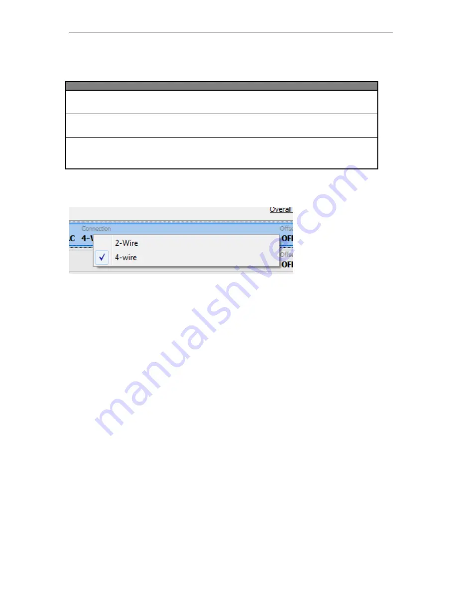
In the column Connection you can select 2-wire or 4-wire measurement. In the case of 4-wire, the power supply

of the sensor takes other wire as the measurement wire. The measurement signal is then not influenced by the
power supply.

Summary of Contents for LTT500

Page 1: ...Manual universal Pre Amplifier LTT500 LTT Labortechnik Tasler GmbH Friedrich Bergius Ring 15 D 97076 Würzburg www tasler de Tel 49 931 359 61 0 Fax 49 931 359 61 50 ...

Page 2: ...n Manual Version 1 6 2 Software of universal Pre Amplifier LTT500 Operation Manual LTT Labortechnik Tasler GmbH Friedrich Bergius Ring 15 D 97076 Würzburg www tasler de Tel 49 931 359 61 0 Fax 49 931 359 61 50 ...

Page 3: ...asler GmbH Al rights reserved Würzburg Deutschland First edition Mai 2010 Document Number 500 2010 1 4 Rev A Contact Labortechnik Tasler GmbH Friedrich Bergius Ring 15 97076 Würzburg Telefon 49 9 31 3 59 61 0 Telefax 49 9 31 3 59 61 50 http www ltt eu ...

Page 4: ...T 22 4 1 SEARCH DEVICE 22 4 2 CHANNEL CONTROL 24 4 2 1 Description of channel control window 24 4 2 2 Selection of channels 26 4 2 3 Channel context 27 4 2 4 Execution mode 28 4 3 KEYBORD SHORTCUTS 28 4 4 ADDITIONAL FUNCTIONS 28 5 CHANNEL SETUP 29 5 1 GENERAL CHANNEL FUNCTIONS 29 5 1 1 Autozero 29 5 1 2 Filter Lowpass 30 5 1 3 Rename channel 30 5 1 4 Channel LEDs blink 30 5 1 5 Copy and Paste of c...

Page 5: ...SETUP 48 6 2 LOAD SETUP 49 6 3 SAVE SETUP 50 7 DEVICE SPECIFIC FUNCTIONS 51 7 1 SAVE CONFIGURATION TO DEVICE 51 7 2 RESET DEVICE TO FACTORY DEFAULT 52 7 3 DEVICE INFORMATION 52 7 4 DEVICE STATUS 52 7 5 LOCK AND UNLOCK THE DEVICE 52 7 6 TURN OFF DEVICE 53 8 TEDS 54 8 1 DETECTION OF TEDS SENSORS 54 8 2 TEDS DATABASE AND CONFIGURATOR 54 9 ADDENDUM A MENU KEYBOARD 57 ...

Page 6: ...e USB or Ethernet cable and the analogue output cable will be connected at the back side of LTT500 In addition it is recommended to connect the Housing Ground of LTT500 with the housing of the following up hardware like f e the LTT184 transient recorder See picture 1 Picture 1 Back side of LTT500 The input channels are located at the front of LTT500 Connect the analogue input cable with the ODU co...

Page 7: ...the LTT logo on the front of the LTT500 the device will switch on To switch off the sensor field must be touched 3 seconds long By software control the switching off can be blocked The power switch symbol will shine red by a touch of your finger if the switching off is blocked from the software ...

Page 8: ... is activated The red LED is on by following error conditions Over Range Cable break Overload of sensor power supply The status details will be indicated in the preAmpLTT software 1 5 Sensor connection Every channel of the LTT500 universal Pre Amplifier has a huge amount of integrated signal conditioning functions The individual function will be activated by software OFF Volt ICP Strain Gauge DMS ...

Page 9: ...n 1 6 9 The ODU Connector The part numbers from ODU are S11 KOC P08MFGO 6500 without bend protection tube S21 KOC P08MFG0 6500 Prepared for protection tube 1 5 3 7 8 Soldering Connector Coding Soldering jack 1 3 7 8 5 Coding ...

Page 10: ...ctor and the second end is open for own configuration The shielded cable offers 4 Twisted Pair lines which are shielded too Die Pin Layout is like following Pin Twisted Pair Colour Name Description 1 D White TD TEDS 2 A Green IN Signal Input 3 A Yellow IN Signal Input 4 B Gray QP Quarter Bridge Power 5 B Pink SN Sensleitung 6 C Blue PO Power Out 7 C Red PO Power Out 8 D Brown GND Channel Ground ...

Page 11: ...t Pin 8 Channel Ground Volt Differential Pin 3 Input Pin 2 Input ICP Sensor Pin 3 Input Pin 2 Input Current measurement Pin 3 Input Pin 2 Input RTD measurment 2 conductor method Pin 3 Input Pin 2 Input RTD measurement 4 conductor method Pin 6 Power Out Pin 3 Input Pin 2 Input Pin 7 Power Out Charge sensor Pin 3 Input Pin 8 Channel Ground ...

Page 12: ...llbridge Pin 6 Power Out Pin 5 Sens Pin 3 Input Pin 2 Input Pin 7 Power Out Strain Gauge Halfbridge Pin 6 Power Out Pin 5 Sens Pin 3 Input Pin 7 Power Out Strain Gauge Quarter bridge Pin 6 Power Out Pin 5 Sense Pin 3 Input Pin 4 Quarter Bridge Power ...

Page 13: ...eAmpLTT software and supplements of the documentation will be published on our webpage http www ltt eu or http www tasler de The newest software versions and documentations will be available in the category Downloads on the webpage above The drawings pictures and screenshots in this manual are exemplary can vary to the software screen you see on your computer It depends on the operation system dis...

Page 14: ...mal 256MB RAM recommended 512 MB Monitor resolution 1 minimal 1024x768 Pixel recommended resolution 1280x1024 Pixel or more USB interface Version 1 1 or more Operation System Microsoft Windows 2000 minimal Service Pack 3 Microsoft Windows 2003 Server Microsoft Windows XP minimal Service Pack 2 Microsoft Vista 1 The preAmpLTT software starts first time with the resolution of 920x600 Pixel A higher ...

Page 15: ...e an folder and you can direct access the files In case of an older operation system you need an software add on like WinZip to access the files inside the Zip achieve At the first installation please generate a folder on your hard disk drive like C Program LTTGMBH Copy both files into the folder you have generated For easy starting the software from your desktop you can generate a link from the f...

Page 16: ...e Version 1 1 1 40 In the case you get some trouble with the newer software version please get urgently in touch with us by e mail or phone Until solving this difficulty you can continue working with the backup of those files A continues updating of those files is recommended as program updates are not only offering new functions its fixing also some bugs inside the program Advice regarding the us...

Page 17: ...arameter are set with standard parameters This chapter will explain you how to change parameters which screens are available at program start and how to initiate the search of devices 3 1 Program start Please start the software via preAmpLTT exe or a direct link to this program Pic 1 preAmpLTT after the first start ...

Page 18: ...e the following steps easier for you In this document the English language is used That means all comments to menu points switches und labeling are based on the English version The scope of operation is independent from the selected language Advice Common expressions protocol information s and technical descriptions f e channel parameter will be not translated There we use the English expression o...

Page 19: ...g enables settings to the program flow and functions Each possible setting will be explained in the following chapter You should not apply any changes there after the first program start The third point in the Options menu opens the editor of the TEDS database This editor is empty after the first start of the software package and will be filled up by recognition or manual adding of TEDS sensor inf...

Page 20: ...ameters as well as the TEDS database will be saved f e at Windows Vista in the user account path of the actual user F e at C Users user name AppData Roaming LTT GmbH The TEDS database is saved in the file named TEDSinfo bin and can be copied from there to any other user account path of another user ...

Page 21: ...hannels can be done Log view This view is always available and gives an extended view on the system and device information In the chapter Operation concept you will get a detailed introduction in the elements of channel control During the daily work with preAmpLTT you can all the time change the view between Home Channel Control and Log view Please take care that f e the channel status information...

Page 22: ...ast one LTT500 universal amplifier was connected with the computer and also switched on the software will automatically find this device After analyzing the channels of this device the software will change to the Channel Control view and will display the actual setting of each channel Pic 4 View of Channel Control when one device was found In case no device was found or the number of devices has c...

Page 23: ... save those settings before the start of rescan devices To avoid any delay in start up of the system switch on first the LTT500 hardware by a short touch on the sensor plate with LTT logo on Wait until the initial sequence the internal relays stop clicking and the blue light behind the sensor plate is shining before starting the preAmpLTT software This procedure avoids a second device search from ...

Page 24: ...ersal amplifier is displayed in one line Each row gives the information about the configuration and status of each channel Pic 5 Channel control with selected channels The first line indicates the channel name its belonging to which device f e Dev 02 channel 4 and the selected type of low pass filter f e 1MHz The second line indicates the selected sensor type OFF means the channel is active but th...

Page 25: ...ay Yellow The status is actual okay but there was an error in the history Red Error on this channel A text with detailed information pops up if you go with the mouse over this status line Above the fifth line you find an additional signal light symbol which indicates an over all status of all channels The highest priority has the error indication which means if one channel shows an error in red th...

Page 26: ...h the standard Microsoft Windows mouse and keyboard combinations With pressed STRG key Rows on different positions will be marked With pressed SHIFT key All rows from the first selection to the actual position will be marked To selct or deselect all channels the check box all channels can be used Pic 6 Select all channels Tick mark the check box to select all channels and unmark the check box to u...

Page 27: ...u of the first column contains general functions The context menu of the second column contains settings regarding the sensor type And so on Pic 7 Contect menu for general functions of channel 1 Please consider that depending on the selected Sensor type and other setting some of the functions are blocked inside the menu The text of those blocked functions is marketed in a light gray color If no ch...

Page 28: ...vigation inside of menus and sub menus there are also several hotkey function integrated Behind some menu name there are the hotkeys mentioned F e the device status can be opened by Strg S Nearly every menu point control element and context has it s own shortcut ALT D opens menu point Device or ALT C opens menu point Channel The important character for the Alt shortcut will be underlined The numbe...

Page 29: ...5 1 General channel functions The context menu of the first column also ALT 1 offers general functions independent of the selected sensor type Pic 9 Context menu general channel functions 5 1 1 Autozero Execute this function to get the output signal of this selected channel s close to zero line Similar to the functions Check UDMS and Check temperature the output of the channel s will shortly show ...

Page 30: ...ce operation If several units are placed over each other it is sometimes hard to identify the right channel connector according to the setup inside the software On this way you can ensure that the right cable sensor is connected on the right channel of the right device in according to the channel setup By executing this function the green and yellow LED of this selected channel will start blinking...

Page 31: ...is function of preAmpLTT It control and display the internal temperature of the LTT500 device by each channel The internally working temperature should be in a range of 25 C to 45 C and the difference between the channels should be up to 10 C Advice The analogue output channel s will be short switched to ground during check temperature procedure Do not start this function if an important measureme...

Page 32: ... or 0dB the output gives the input signal 1 1 out Following input ranges can be selected As next you select in the column Coupling the input coupling circuit for this channel You can decide between following configurations Coupling ODU Pin Description Single Ended DC Pin 3 Pin 8 Input Signal Ground Single Ended DC Pin 2 Pin 8 Input Signal Ground Differential Ended DC Differential Ended 3Hz High Pa...

Page 33: ...t Constant current Pin 6 Pin 7 Power Out Power Out Constant voltage Based to ground Select the double value of the voltage Pin 6 Pin 8 Power Out Ground The voltage power supply has a symmetric design That means by selecting 10V supply the output is 5V between pin 6 and 7 In the case you need an unsymmetrical power supply from 10V against channel ground you have to select 20V supply in the software...

Page 34: ...ed DC Pin 3 Pin 2 Input Input In seldom cases Differential Ended DC makes sense if a quasi static sensor signal needs to be observed In such a case the sensor signal has an offset and you should not select a to small measurement range The current supply is done over pin 3 and 2 That means two lines for signal and power supply together is enough No other pins are required The value of current can b...

Page 35: ... pin layout is like following Connection type Pin Layout Description Strain Gauge Fullbridge Pin 6 Power Out Pin 5 Sense Pin 3 Input Pin 2 Input Pin 7 Power Out The differential input signal of this channel will be outputted on its output The amplification or attenuation depends on the selected input range in the next column With the range 5V 1 1 or 0dB the output gives the input signal 1 1 out Fo...

Page 36: ...gnal between Input und Input will be amplified and outputted Differential Ended 3Hz High Pass Filter As Differential Ended DC but the signal will be filtered by a 3Hz high pass No DC components of the measurement signal will be outputted The column Resistor enables the selection of the bridge and bridge complement resistor This selection is not needed in case of a full bridge In the column Shunt a...

Page 37: ...ply directly at the sensor On this way the power drop on the cable to the sensor can be compensated The LTT500 use just one sense line 5 line technology Because of the symmetric sensor power supply one line is enough The negative power supply is compensated too In the column Supply the value of the sensor power supply is selected ...

Page 38: ...mn Coupling the input coupling of the channel You have the choise between Coupling Description Zero Input and Input will be shorten to channel ground The output signal is 0V Differential Ended DC The differential signal between Input und Input will be amplified and outputted Differential Ended 3Hz High Pass Filter As Differential Ended DC but the signal will be filtered by a 3Hz high pass No DC co...

Page 39: ...a standard always another common resistance value you can ask LTT to equip the inputs already with your right resistor value In the column Shunt a shunt resistor with 100kΩ can be switched on to unbalance the bridge with a defined value In the column Sense a sense line can be activated to control the bridge power supply directly at the sensor On this way the power drop on the cable to the sensor c...

Page 40: ...f the bridge is connected to the input The rest of the bridge is completed inside of the device Connection type Pin Layout Description Strain Gauge quarterbridge Pin 6 Power Out Pin 5 Sens Pin 3 Input Pin 4 Quarter Bridge Power Important Inside of the ODU connector Pin 3 and 4 needs to be shorten As next select in the column Coupling the input coupling of the channel You have the choise between ...

Page 41: ...bles the selection of the bridge and bridge complement resistor In case you bridge is build by 120Ω resistors you select 120 Ohm In case your bridge is build by 350Ω resistors you select 350 Ohm In the non common case your bridge has higher resistant values select fullbridge as sensor type and build the bridge completion externally with the right resistor values If you have a standard always anoth...

Page 42: ...ation Manual Version 1 6 42 line technology Because of the symmetric sensor power supply one line is enough The negative power supply is compensated too In the column Supply the value of the sensor power supply is selected ...

Page 43: ...below safety comment Caution The signal Input and Input pin 3 and 2 will be shorten by an internally 25Ω resistor Please ensure that no current over 125mA will be applied In other cases the internal circuit can be damaged Please select Yes if you are sure to start the current measurement mode Connection type Pin Layout Description Current measurement Pin 3 Input Pin 2 Input As next select the inpu...

Page 44: ... have the choise between Coupling Description Differential Ended DC The differential signal between Input und Input will be amplified and outputted Differential Ended 3Hz High Pass Filter As Differential Ended DC but the signal will be filtered by a 3Hz high pass No DC components of the measurement signal will be outputted ...

Page 45: ...oltage drop over the PT100 resistor will be outputted The measured voltage is proportional to the temperature at the PT100 Connection type Pin Layout Description RTD measurement 2 Wire technology Pin 3 Input Pin 2 Input RTD measurement 4 Wire technology Pin 6 Power Out Pin 3 Input Pin 2 Input Pin 7 Power Out As next select in the column Coupling the input coupling of the channel You have the chois...

Page 46: ...amplified and outputted Differential Ended 3Hz High Pass Filter As Differential Ended DC but the signal will be filtered by a 3Hz high pass No DC components of the measurement signal will be outputted In the column Connection you can select 2 wire or 4 wire measurement In the case of 4 wire the power supply of the sensor takes other wire as the measurement wire The measurement signal is then not i...

Page 47: ...l slightly Pic 11 Dialog with switched off and on Offset electronic The setting of Offset is related to the selected input range of the channel The value is in percentage of the Full Scale Range FSR The maximum percentage of offset is related to the selected input range 50V 5V and 500 mV 100 to 100 FSR is possible Lower input ranges 200 to 200 FSR is possible The needed offset can be setup by the ...

Page 48: ...al number In every saved setup the serial number of the channel is registered Independent of the sorting and number of devices the software load a setting back to the right channel of the right device 6 1 Default setup To get the device back to a save default setup you can press the Hotkey F2 or went to the menu File Default setup Default setup Hotkey F2 This function reset all active channels to ...

Page 49: ... channels or devices or channel serial numbers The software offers the possibility to load the setup too If you confirm the setup will be loaded in the sequence as the devices was first recognized by the computer That means at a multi device configuration the sequence of channel configurations can be different as expected In the first case the setup will be loaded without interruption In the secon...

Page 50: ...ve setup The dialog will ask you for a file name and the directory The ending of file name will be always prs If you enter a file name which already exist you will be ask to overwrite it Save setup Hotkey F4 Please use this function if you would like to reuse the configuration in future Give the file name on a way that you will later know for which application you have used it ...

Page 51: ...n its memory By switching on the LTT500 the device loads its internal saved configuration The standard is the factory default The actual channel setup of the software will be transferred and saved on the LTT500 by the menu point Device Save config to device Before starting the transfer a dialog popup which needs to be confirmed This popup window can be deactivated by the menu point Device Settings...

Page 52: ...ts hardware version Please save this information in a service case an send it by e mail to LTT 7 4 Device status The function Device Device status or the hotkey Strg S open a window with status informations The information s are Fan rotation speed Power supply voltage and current consumption of the selected channel s This window needs not to be closed for the normal operation of the software By pr...

Page 53: ... point Device Turn off device to switch off all connected LTT500 devices In case Device Setting Warn before turn off device is activated a popup window comes up and as to save the actual configuration before switching off the device s After confirmation this request the device will switch off ...

Page 54: ...S Add new TEDS information to configuration list is not check marked A known TEDS Unique ID was found The pre saved channel setup will be loaded to the right channel Nothing happens if the menu point Device Settings TEDS Apply configuration on existing TEDS information is not check marked The actual preAmpLTT software supports only the reading of the UNIQUE ID and cannot read the TEDS sensor confi...

Page 55: ... entry s can be modified With the key Edit the contents can be modified To modify one entry in the list mark the entry and press Edit A new window will come up to enter the sensor type and its relevant other channel setting You can enter also some comments to the sensor and give a own name to the sensor ...

Page 56: ...8 TEDS Operation Manual Version 1 6 56 Pic 14 Individual channel cofigurator Please keep in mind that all modifications inside the window will become only valid if you finish the entry by Apply key ...

Page 57: ... keyboard Menu structure and hotkey combinations File Default setup F2 Load setup F3 Save setup F4 Rescan for device F12 Exit Alt F4 Edit Cut Strg X Copy Strg C Paste Strg V Select all Strg A View Home Channel control Log files Refresh F5 Options Language Settings TEDS Database ...

Page 58: ...ault Device information Strg I Device status Strg S Lock device Unlock device Turn off device s Channel Extended channel information Alt I Channel context Alt 1 Sensor selection Alt 2 Range selection Alt 3 Coupling Alt 4 Resistor Alt 5 Shunt Alt 6 Sense Alt 7 2 Wire 4 Wire Alt 8 Current Supply Alt 9 Offset Alt 0 Help About ...

Reviews: