
TASCAM TM-D1000 Operations Manual
34
13 - Options
A number of options are available for the TM-
D1000, as described here.
13.1RM-D1000 rack mounting kit
The RM-D1000 rack mounting kit allows the TM-
D1000 to be mounted in 6U of rack space (in addi-
tion to space needed at the top for the connectors).
You should also ensure that the rack is well-venti-
lated, allowing air to circulate for cooling the heat
sink of the TM-D1000.
1
The wristpad below the faders should be
unscrewed before mounting the TM-D1000
in a rack.
2
Attach the two rack mounts to the TM-
D1000 using the five screws (provided) on
each mount.
3
Fit the TM-D1000 into the rack, allowing
enough space at the top for cables to be fitted
to the connectors.
13.2IF-TD1000 Digital Input Kit
This kit provides two more sets of digital inputs
(XLR and RCA), capable of receiving AES/EBU or
SPDIF format, as well as another TDIF-1 connector,
for another eight channels of DTRS-compatible
audio.
WARNING
This kit requires internal connections to the
TM-D1000. For this reason, you should not
install the kit yourself, but should refer instal-
lation to a qualified TASCAM distributor.
The digital inputs are labeled
B
and
C
. Digital input
B is available as an extra option in the following
menus where input
A
is available:
•
Setup
➠
Digital Input
•
Setup
➠
Aux Rtn Input/
Assign
•
Setup
➠
Eff Return
Input/Assign
Digital input C is treated differently, on account of
the frequency conversion facility built into digital
input
C
. An additional menu is available when the IF-
TD1000 Digital I/O Board is fitted, which allows
input channels 7 and 8 to be assigned to digital input
C
or to the analog inputs, for all menus using these
inputs.
This sub-menu is available from the Setup options,
and appears as follows:
Use the data entry knob to choose between
Digital In C
and
Analog
.
As well as the additional stereo digital inputs, the IF-
TD1000 Digital I/O Board also provides another
TDIF-1 connector (TDIF-1 B). This set of 8 channels
is available for use by the input channels, as set in the
following menus:
•
Setup
➠
Ch1-8 Input
•
Setup
➠
Ch9-16 Input
•
System
➠
TDIF-1 A/B
Word Length
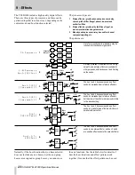
The routing of group busses to the second TDIF-1
channel follows the pattern of the routing to the first
channel (i.e. if groups 1 & 2 are routed to TDIF-1 A
C h 7 - 8
R o u t e 1
T a r g e t
D i g i t a l
I n
C ?


