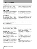
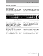
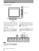
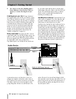
Tascam SX-1 Quick Start Manual Download Page 7

Chapter 1 –Introduction

 TASCAM SX-1 

Quick Start Guide

 7

Unpacking

The SX-1 was carefully packed at our factory in a 
special box to avoid damage during shipping. Still, 
damage can occur if the box was mishandled or 
dropped. If you notice any visible damage to the SX-
1 itself, notify the TASCAM dealer where you pur-
chased your SX-1 as soon as possible.

WARNING

The SX-1 is a heavy machine and we strongly recom-
mend not lifting it out of the box by yourself. To avoid 
injury, have at least one other person assist you in mov-
ing the SX-1 to its desired location.

We also suggest holding onto the original box, and 
all of its associated packing materials, that the unit 
came in. This will ensure that, in the unlikely event 
you need to ship the SX-1 back to TASCAM for ser-
vicing, you will have all the necessary shipping 
materials.

Box Contents

Before beginning to set up your SX-1, make sure that 
your unit came with all the proper paperwork and 
connections. There's nothing more frustrating than 
trying to figure out where a missing part is in the 
middle of hooking up your studio.

Your SX-1 carton should contain the following 
items:

SX-1 Digital Production Environment

IEC Type II Power Cable

Software  CD-ROM

CD-ROM (documentation)

PS/2 keyboard and mouse

Quick Start Guide

Owner's Manual

Warranty Card and other important papers

Registration

Please be sure to register your new SX-1 by complet-
ing and mailing the unit's Warranty Card. If you don't 
register your machine we will not be able to inform 
you of software upgrades. We are constantly working 

to improve and expand the SX-1 and we want to 
make sure your machine is always up to date. Regis-
tering your SX-1 will ensure that you are always get-
ting the most out of your unit.

Options

On top of all the SX-1's wonderful stock features, 
there are also a wealth of expansion card options 
available. Listed here are just some of the current 
options (for pricing and availability, check with your 
authorized TASCAM dealer).

I/O Expansion Cards

TDIF digital I/O up to 24-channels (IF-TD/DM)

ADAT Optical I/O up to 24 more channels (IF-
AD/DM)

AES/EBU I/O up to 24-channels (IF-AE/DM)

Analog I/O up to 24 more channels (IF-AN/DM)

Support and Updates

The SX-1 is easily updated via its onboard CD-ROM 
drive. TASCAM will mail registered owners operat-
ing system (OS) updates on CD-ROM when they 
become available. Details for updating your unit's OS 
are covered here and in the 

Owner's Manual

. And of 

course, if you do run into problems, as a registered 
owner you have one of the best technical support 
teams in the industry at your disposal.

You may also want to visit the TASCAM Web site 
(http://www.tascam.com) for late-breaking news and 
details regarding the SX-1.
TASCAM's support staff can answer all of your ques-
tions and help you troubleshoot any problems that 
may arise.

Summary of Contents for SX-1

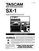
Page 1: ...erature accompanying the appliance The lightning flash with arrowhead symbol within an equilateral triangle is intended to alert the user to the presence of uninsulated dangerous voltage within the pr...

Page 2: ...er IF IN DOUBT CONSULT A COMPETENT ELECTRICIAN TO THE USER This equipment has been tested and found to comply with the limits for a Class A digital device pursuant to Part 15 of the FCC Rules These li...

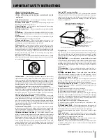
Page 3: ...pporting structure grounding of the lead in wire to an antenna discharge unit size of grounding conductors location of antenna discharge unit connection to grounding electrodes and require ments for t...

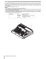
Page 4: ...label required in this regulation is shown in 1 CAUTION DO NOT REMOVE THE PROTECTIVE HOUSING USING A SCREWDRIVER USE OF CONTROLS OR ADJUSTMENTS OR PERFORMANCE OF PROCEDURES OTHER THAN THOSE SPECIFIED...

Page 5: ...VGA screen 23 From the LCD screen 24 Shutdown Procedure 24 Chapter 6 Taking Control Audio Monitoring 26 Information Display 26 Mix Control 26 Settings Management 26 MIDI 27 Editing 27 Transport and Da...

Page 6: ...r 100mm touch sensitive moving faders 16 fader layers seven freely assignable by user 16 high quality mic preamps with phantom power Highly flexible signal routing Mastering Record 2 track masters and...

Page 7: ...other important papers Registration Please be sure to register your new SX 1 by complet ing and mailing the unit s Warranty Card If you don t register your machine we will not be able to inform you of...

Page 8: ...on the SX 1 itself For example the Play button is written PLAY In the case where a key has more than one function for example a main and shift function the Shifted function is explained on Multi Funct...

Page 9: ...rols serve as a channel s pan pot EQ Aux sends or pan for the cue mix The virtual pots are surrounded by a ring of LEDs which indicate their current setting For exam ple a pan pot that is hard left wi...

Page 10: ...Keypad To adjust the viewing angle and contrast of the LCD use the small contrast knob to the top right of the LCD LCD or VGA You have a choice of using the LCD or an VGA dis play as your main screen...

Page 11: ...first 32 mixer channels the faders also control the cue mix MIDI tracks sends returns and busses Different groups of faders called fader banks are accessed by the keys in the FADER BANKS section on th...

Page 12: ...e con sole but there are also several crucial connections on the unit s rear MIDI VGA output mouse PS 2 key board expansion ports and digital I O When posi tioning your SX 1 you should make sure there...

Page 13: ...d mouse and keyboard are required for navi gating an external VGA display the mouse and key board ports are found on the unit s rear Important Rear Connections on page 17 When using an exter nal displ...

Page 14: ...does not have grounded outlets contact a professional electrician about installing an earthed ground Avoiding Ground Loops A ground loop occurs when a piece of equipment sees more than one path to gro...

Page 15: ...e Talkback mic to a variety of other destinations for more on this feature see the chapter that explains the Talkback mic in the Owner s Manual Control Room 3 CONTROL ROOM The Control Room out puts ar...

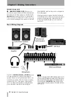
Page 16: ...toring levels independently without affecting the level going from the Master out to a 2 track mix down deck Basic Wiring Diagram The SX 1 s CONTROL ROOM and STUDIO outs can be connected directly to...

Page 17: ...Video sync signal also called house sync or black burst to the VIDEO IN VIDEO THRU will pass that same signal directly out unaffected by any of the SX 1 s electronics The Sony 9 pin connector also kno...

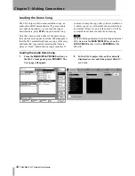
Page 18: ...ning that there is always a clean demonstration song available If you want to keep the copy after you have worked on it unless you save it with another name which does not include Demo as part of the...

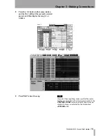
Page 19: ...ad the currently selected project and then display the song s Track window 4 Press PLAY to hear the song TIP If you don t hear anything make sure that the source feeding your monitors is the stereo ou...

Page 20: ...rformance and synchro nization data Connect your controller s MIDI output to the SX 1 s jack labeled MIDI IN and connect the SX 1 s MIDI OUTs to the inputs of your MIDI sound modules MIDI controlled e...

Page 21: ...al MIDI performance data then just press PLAY to hear the MIDI song If not read the directions below on how to change a MIDI track s channel to match your sound module s MIDI channel TIP To hear sound...

Page 22: ...ed 4 Next go to the MIDI channel select menu and choose the channel that corresponds to the MIDI channel your sound module is set to receive In the VGA window this is done through a second pull down m...

Page 23: ...ack up is to use the SX 1 s onboard CD R burner Follow the steps below to find out just how easy it is TIP HOT TIP We recommend using TEAC brand CD recordable media for all your CD R needs From the VG...

Page 24: ...ess the BACKUP soft key The SX 1 will pre pare all the data to be backed up and burn the CD after which the disc will be ejected 5 You re finished You have successfully backed up a project Shutdown Pr...

Page 25: ...ok for a particular function For easy reference here is a diagram of the SX 1 s control sections The face of the SX 1 is separated into a number of different control sections Most sections have a clea...

Page 26: ...ion 5 Information Display This section is not actually labeled Information Display on the SX 1 However that title best describes this area Here you will find the LCD stereo meters and a variety of LED...

Page 27: ...Data Entry C TRANSPORT Though this area is not actually labeled Transport on the SX 1 that title best describes this section of the SX 1 s face Here you will find a set of standard transport keys pla...

Page 28: ...t Slots can be moved or modified with or without loaded Takes and that anything done to a Slot is done to a Take loaded upon it meaning that if you delete a Slot its Take is automatically unloaded Tak...

Page 29: ...r the rest of your system Creating a New Project The SX 1 automatically saves the last project you were working on when you perform the Shutdown procedure It will also automatically reload that last p...

Page 30: ...is connected to analog input 1 on the top panel On the VGA 1 On the Track page locate the slots on the left side of the screen and click the icon with the mouse next to the icon 2 From the pulldown m...

Page 31: ...simply verify the input or the output of the Take you can use the Select Source and Select Dest soft knobs to see what is currently selected for each and to change the setting if you wish 4 Press the...

Page 32: ...ressing the MIDI A key in the FADER BANKS section of the slanted front panel and then pressing the REC arm key for MIDI A Channel 1 6 Make sure you have remembered to bring up the audio faders where y...

Page 33: ...dicators flash in various places letting you know that the time value you just captured can be stored in any of them 3 Press the LOCATE key in the LOCATE section 4 Press a number on the numeric keypad...

Page 34: ...y 3 Power down the SX 1 4 When the SX 1 is fully shut down reboot the machine 5 The normal boot sequence will be inter rupted with the software CD ROM in the drive A prompt will appear asking you if y...

Page 35: ...AUX SEND 1 4 and STEREO OUT jacks to an external headphone amplifier This means that you now have 5 mixes running at the same time The Stereo Mix you are listening to in the Control Room the Cue Mix...

Page 36: ...t comped together to save space and load in the new pair You can re import these Takes in the same way you would normally load Takes into a project Quickly use the LCD and the VGA screens to show sepa...

Page 37: ...to a number of tra ditional computer style commands One such com mand is the use of the Tab key on the PS 2 keyboard You can use this key to jump quickly between text fields of a similar type like th...

Page 38: ...ness Park Watford Hertfordshire WD1 8TE U K TEAC DEUTSCHLAND GmbH Phone 0611 71580 Bahnstrasse 12 65205 Wiesbaden Erbenheim Germany TEAC FRANCE S A Phone 01 42 37 01 02 17 Rue Alexis de Tocqueville CE...

Reviews: