Tascam SX-1 Quick Start Manual Download Page 3

 TASCAM SX-1 Quick Start Guide 

3

CAUTION:

Read all of these Instructions.

Save these Instructions for later use.

Follow all Warnings and Instructions marked on the audio
equipment.

1) Read Instructions

 — All the safety and operating instructions

should be read before the product is operated.

2) Retain Instructions 

— The safety and operating instructions

should be retained for future reference.

3) Heed Warnings

 — All warnings on the product and in the operating

instructions should be adhered to.

4) Follow Instructions

 — All operating and use instructions should be

followed.

5) Cleaning

 — Unplug this product from the wall outlet before clean-

ing. Do not use liquid cleaners or aerosol cleaners. Use a damp cloth for
cleaning.

6) Attachments

 — Do not use attachments not recommended by the

product manufacturer as they may cause hazards.

7) Water and Moisture

 — Do not use this product near water — for

example, near a bath tub, wash bowl, kitchen sink, or laundry tub; in a
wet basement; or near a swimming pool; and the like.

8) Accessories

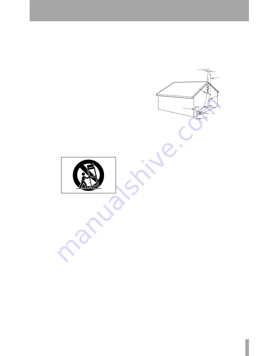
 — Do not place this product on an unstable cart, stand,

tripod, bracket, or table. The product may fall, causing serious injury to a
child or adult, and serious damage to the product. Use only with a cart,
stand, tripod, bracket, or table recommended by the manufacturer, or sold
with the product. Any mounting of the product should follow the manu-
facturer’s instructions, and should use a mounting accessory recom-
mended by the manufacturer.

9)

 A product and cart combination should be moved with care. Quick

stops, excessive force, and uneven surfaces may cause the product and
cart combination to overturn.

10)


Ventilation

 — Slots and openings in the cabinet are provided for

ventilation and to ensure reliable operation of the product and to protect
it from overheating, and these openings must not be blocked or covered.
The openings should never be blocked by placing the product on a bed,
sofa, rug, or other similar surface. This product should not be placed in a
built-in installation such as a bookcase or rack unless proper ventilation
is provided or the manufacturer’s instructions have been adhered to.

11) Power Sources

 — This product should be operated only from the

type of power source indicated on the marking label. If you are not sure
of the type of power supply to your home, consult your product dealer or
local power company. For products intended to operate from battery
power, or other sources, refer to the operating instructions.

12) Grounding or Polarization

 — This product may be equipped

with a polarized alternating-current line plug (a plug having one blade
wider than the other). This plug will fit into the power outlet only one
way. This is a safety feature. If you are unable to insert the plug fully into
the outlet, try reversing the plug. If the plug should still fail to fit, contact
your electrician to replace your obsolete outlet. Do not defeat the safety
purpose of the polarized plug.

13) Power-Cord Protection

 — Power-supply cords should be routed

so that they are not likely to be walked on or pinched by items placed
upon or against them, paying particular attention to cords at plugs, con-
venience receptacles, and the point where they exit from the product.

14) Outdoor Antenna Grounding

 — If an outside antenna or cable

system is connected to the product, be sure the antenna or cable system is
grounded so as to provide some protection against voltage surges and
built-up static charges. Article 810 of the National Electrical Code,
ANSI/NFPA 70, provides information with regard to proper grounding
of the mast and supporting structure, grounding of the lead-in wire to an
antenna discharge unit, size of grounding conductors, location of
antenna-discharge unit, connection to grounding electrodes, and require-
ments for the grounding electrode.

"Note to CATV system installer:

This reminder is provided to call the CATV system installer’s attention
to Section 820-40 of the NEC which provides guidelines for proper
grounding and, in particular, specifies that the cable ground shall be con-
nected to the grounding system of the building, as close to the point of
cable entry as practical.

15) Lightning

 — For added protection for this product during a light-

ning storm, or when it is left unattended and unused for long periods of
time, unplug it from the wall outlet and disconnect the antenna or cable
system. This will prevent damage to the product due to lightning and
power-line surges.

16) Power Lines

 — An outside antenna system should not be located

in the vicinity of overhead power lines or other electric light or power
circuits, or where it can fall into such power lines or circuits. When
installing an outside antenna system, extreme care should be taken to
keep from touching such power lines or circuits as contact with them
might be fatal.

17) Overloading

 — Do not overload wall outlets, extension cords, or

integral convenience receptacles as this can result in risk of fire or elec-
tric shock.

18) Object and Liquid Entry

 — Never push objects of any kind into

this product through openings as they may touch dangerous voltage
points or short-out parts that could result in a fire or electric shock. Never
spill liquid of any kind on the product.

19) Servicing

 — Do not attempt to service this product yourself as

opening or removing covers may expose you to dangerous voltage or
other hazards. Refer all servicing to qualified service personnel.

20) Damage Requiring Service

 — Unplug this product from the

wall outlet and refer servicing to qualified service personnel under the
following conditions:

a)

when the power-supply cord or plug is damaged.

b)

if liquid has been spilled, or objects have fallen into the product.

c)

if the product has been exposed to rain or water.

d)

if the product does not operate normally by following the operating

instructions. Adjust only those controls that are covered by the operating
instructions as an improper adjustment of other controls may result in
damage and will often require extensive work by a qualified technician to
restore the product to its normal operation.

e)

if the product has been dropped or damaged in any way.

f )

when the product exhibits a distinct change in performance – this

indicates a need for service.

21) Replacement Parts

 — When replacement parts are required, be

sure the service technician has used replacement parts specified by the
manufacturer or have the same characteristics as the original part. 
Unauthorized substitutions may result in fire, electric shock, or other
hazards.

22) Safety Check

 — Upon completion of any service or repairs to this

product, ask the service technician to perform safety checks to determine
that the product is in proper operating condition.

23) Wall or Ceiling Mounting

 — The product should be mounted to a

wall or ceiling only as recommended by the manufacturer.

24) Heat 

— The product should be situated away from heat sources such

as radiators, heat registers, stoves, or other products (including amplifi-
ers) that produce heat.

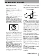
ANTENNA
LEAD IN
WIRE

ANTENNA
DISCHARGE UNIT
(NEC SECTION 810-20)

G

ROUNDING CONDUCTORS

(NEC SECTION 810-21)

GROUND CLAMPS

POWER SERVICE GROUNDING
ELECTRODE SYSTEM
(NEC ART 250. PART H)

NEC - NATIONAL ELECTRICAL CODE

ELECTRIC
SERVICE
EQUIPMENT

Example of Antenna Grounding as per

National Electrical Code, ANSI/NFPA 70

GROUND
CLAMP

IMPORTANT SAFETY INSTRUCTIONS

Summary of Contents for SX-1

Page 1: ...erature accompanying the appliance The lightning flash with arrowhead symbol within an equilateral triangle is intended to alert the user to the presence of uninsulated dangerous voltage within the pr...

Page 2: ...er IF IN DOUBT CONSULT A COMPETENT ELECTRICIAN TO THE USER This equipment has been tested and found to comply with the limits for a Class A digital device pursuant to Part 15 of the FCC Rules These li...

Page 3: ...pporting structure grounding of the lead in wire to an antenna discharge unit size of grounding conductors location of antenna discharge unit connection to grounding electrodes and require ments for t...

Page 4: ...label required in this regulation is shown in 1 CAUTION DO NOT REMOVE THE PROTECTIVE HOUSING USING A SCREWDRIVER USE OF CONTROLS OR ADJUSTMENTS OR PERFORMANCE OF PROCEDURES OTHER THAN THOSE SPECIFIED...

Page 5: ...VGA screen 23 From the LCD screen 24 Shutdown Procedure 24 Chapter 6 Taking Control Audio Monitoring 26 Information Display 26 Mix Control 26 Settings Management 26 MIDI 27 Editing 27 Transport and Da...

Page 6: ...r 100mm touch sensitive moving faders 16 fader layers seven freely assignable by user 16 high quality mic preamps with phantom power Highly flexible signal routing Mastering Record 2 track masters and...

Page 7: ...other important papers Registration Please be sure to register your new SX 1 by complet ing and mailing the unit s Warranty Card If you don t register your machine we will not be able to inform you of...

Page 8: ...on the SX 1 itself For example the Play button is written PLAY In the case where a key has more than one function for example a main and shift function the Shifted function is explained on Multi Funct...

Page 9: ...rols serve as a channel s pan pot EQ Aux sends or pan for the cue mix The virtual pots are surrounded by a ring of LEDs which indicate their current setting For exam ple a pan pot that is hard left wi...

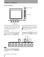
Page 10: ...Keypad To adjust the viewing angle and contrast of the LCD use the small contrast knob to the top right of the LCD LCD or VGA You have a choice of using the LCD or an VGA dis play as your main screen...

Page 11: ...first 32 mixer channels the faders also control the cue mix MIDI tracks sends returns and busses Different groups of faders called fader banks are accessed by the keys in the FADER BANKS section on th...

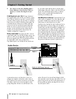
Page 12: ...e con sole but there are also several crucial connections on the unit s rear MIDI VGA output mouse PS 2 key board expansion ports and digital I O When posi tioning your SX 1 you should make sure there...

Page 13: ...d mouse and keyboard are required for navi gating an external VGA display the mouse and key board ports are found on the unit s rear Important Rear Connections on page 17 When using an exter nal displ...

Page 14: ...does not have grounded outlets contact a professional electrician about installing an earthed ground Avoiding Ground Loops A ground loop occurs when a piece of equipment sees more than one path to gro...

Page 15: ...e Talkback mic to a variety of other destinations for more on this feature see the chapter that explains the Talkback mic in the Owner s Manual Control Room 3 CONTROL ROOM The Control Room out puts ar...

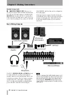
Page 16: ...toring levels independently without affecting the level going from the Master out to a 2 track mix down deck Basic Wiring Diagram The SX 1 s CONTROL ROOM and STUDIO outs can be connected directly to...

Page 17: ...Video sync signal also called house sync or black burst to the VIDEO IN VIDEO THRU will pass that same signal directly out unaffected by any of the SX 1 s electronics The Sony 9 pin connector also kno...

Page 18: ...ning that there is always a clean demonstration song available If you want to keep the copy after you have worked on it unless you save it with another name which does not include Demo as part of the...

Page 19: ...ad the currently selected project and then display the song s Track window 4 Press PLAY to hear the song TIP If you don t hear anything make sure that the source feeding your monitors is the stereo ou...

Page 20: ...rformance and synchro nization data Connect your controller s MIDI output to the SX 1 s jack labeled MIDI IN and connect the SX 1 s MIDI OUTs to the inputs of your MIDI sound modules MIDI controlled e...

Page 21: ...al MIDI performance data then just press PLAY to hear the MIDI song If not read the directions below on how to change a MIDI track s channel to match your sound module s MIDI channel TIP To hear sound...

Page 22: ...ed 4 Next go to the MIDI channel select menu and choose the channel that corresponds to the MIDI channel your sound module is set to receive In the VGA window this is done through a second pull down m...

Page 23: ...ack up is to use the SX 1 s onboard CD R burner Follow the steps below to find out just how easy it is TIP HOT TIP We recommend using TEAC brand CD recordable media for all your CD R needs From the VG...

Page 24: ...ess the BACKUP soft key The SX 1 will pre pare all the data to be backed up and burn the CD after which the disc will be ejected 5 You re finished You have successfully backed up a project Shutdown Pr...

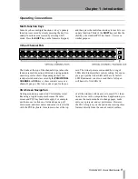
Page 25: ...ok for a particular function For easy reference here is a diagram of the SX 1 s control sections The face of the SX 1 is separated into a number of different control sections Most sections have a clea...

Page 26: ...ion 5 Information Display This section is not actually labeled Information Display on the SX 1 However that title best describes this area Here you will find the LCD stereo meters and a variety of LED...

Page 27: ...Data Entry C TRANSPORT Though this area is not actually labeled Transport on the SX 1 that title best describes this section of the SX 1 s face Here you will find a set of standard transport keys pla...

Page 28: ...t Slots can be moved or modified with or without loaded Takes and that anything done to a Slot is done to a Take loaded upon it meaning that if you delete a Slot its Take is automatically unloaded Tak...

Page 29: ...r the rest of your system Creating a New Project The SX 1 automatically saves the last project you were working on when you perform the Shutdown procedure It will also automatically reload that last p...

Page 30: ...is connected to analog input 1 on the top panel On the VGA 1 On the Track page locate the slots on the left side of the screen and click the icon with the mouse next to the icon 2 From the pulldown m...

Page 31: ...simply verify the input or the output of the Take you can use the Select Source and Select Dest soft knobs to see what is currently selected for each and to change the setting if you wish 4 Press the...

Page 32: ...ressing the MIDI A key in the FADER BANKS section of the slanted front panel and then pressing the REC arm key for MIDI A Channel 1 6 Make sure you have remembered to bring up the audio faders where y...

Page 33: ...dicators flash in various places letting you know that the time value you just captured can be stored in any of them 3 Press the LOCATE key in the LOCATE section 4 Press a number on the numeric keypad...

Page 34: ...y 3 Power down the SX 1 4 When the SX 1 is fully shut down reboot the machine 5 The normal boot sequence will be inter rupted with the software CD ROM in the drive A prompt will appear asking you if y...

Page 35: ...AUX SEND 1 4 and STEREO OUT jacks to an external headphone amplifier This means that you now have 5 mixes running at the same time The Stereo Mix you are listening to in the Control Room the Cue Mix...

Page 36: ...t comped together to save space and load in the new pair You can re import these Takes in the same way you would normally load Takes into a project Quickly use the LCD and the VGA screens to show sepa...

Page 37: ...to a number of tra ditional computer style commands One such com mand is the use of the Tab key on the PS 2 keyboard You can use this key to jump quickly between text fields of a similar type like th...

Page 38: ...ness Park Watford Hertfordshire WD1 8TE U K TEAC DEUTSCHLAND GmbH Phone 0611 71580 Bahnstrasse 12 65205 Wiesbaden Erbenheim Germany TEAC FRANCE S A Phone 01 42 37 01 02 17 Rue Alexis de Tocqueville CE...

Reviews: