


7
SAFETY
(Safety continued on next page)
Before detaching power unit or performing any
service or maintenance, follow these steps: disengage
power to equipment, lower the 3-point hitch and all
raised components to the ground, set parking brake,
stop engine, remove key, and unfasten seat belt.
Before performing any service or maintenance,
disconnect driveline from tractor PTO.
Before working underneath, carefully read Operator’s
Manual instructions, disconnect driveline, raise
implement, securely block up all corners with jack
stands, and check stability. Secure blocking prevents
equipment from dropping due to hydraulic leak down,
hydraulic system failures, or mechanical component
failures.
Do not modify, alter, or permit anyone else to modify or
alter the equipment or any of its components in any way.
Always wear relatively tight and belted clothing to avoid
getting caught in moving parts. Wear sturdy, rough-
soled work shoes and protective equipment for eyes,
hair, hands, ears, and head; wear respirator or filter mask
where appropriate.
Make sure implement is properly secured, adjusted, and
in safe operating condition.
Keep all persons away from operator control area while
performing adjustments, service, or maintenance.
Never go underneath equipment (lowered to the ground
or raised) unless it is properly blocked and secured.
Never place any part of the body underneath equipment
or between moveable parts even when the engine has
been turned off. Hydraulic system leak down, hydraulic
system failures, mechanical failures, or movement of
control levers can cause equipment to drop or rotate
unexpectedly and cause severe injury or death. Follow
Operator’s Manual instructions for working underneath
and blocking procedures.
Make certain all movement of equipment components
has stopped before approaching for service.
Frequently check blades/tines/shanks. They should be
sharp, free of nicks and cracks, and securely fastened.
Do not handle blades/tines/shanks with bare hands.
Careless or improper handling may result in serious
injury.
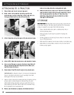
STORAGE
Block equipment securely for storage.
Keep children and bystanders away from storage area.
Follow manual instructions for storage.
Always use a tractor to position equipment for storage.
Never attempt to move equipment by hand.
EQUIPMENT SAFETY GUIDELINES
Safety of the operator and bystanders is one of the
main concerns in design and development. However,
accidents always occur which could have been avoided
by a few seconds of thought and a more careful approach
to handling equipment. You, the operator, can avoid
many accidents by observing the following precautions
and insist those working with you, follow them.
In order to provide a better view, certain photographs or
illustrations in this manual may show an assembly with a
safety shield removed. However, equipment should never
be operated in this condition. Keep all shields in place. If
shield removal becomes necessary for repairs, replace the
shield prior to use.
Replace any safety sign that is illegible or missing.
Location of such safety signs are indicated in this manual.
Never use alcoholic beverages or drugs that can hinder
alertness or coordination while operating this equipment.
Consult your doctor about operating this machine while
taking prescription medications.
Under no circumstances should children under the
age of 18 be allowed to operate this equipment. Do not
allow persons to operate or assemble this unit until they
have read this manual and have developed a thorough
understanding of the safety precautions and how it works.
Review the safety instructions with all users annually.
This equipment can be dangerous to children and
persons unfamiliar with its operation. The operator should
be a responsible, properly trained and physically able
person familiar with farm machinery and trained in this
equipment’s operations.
Use a tractor equipped with a Roll Over Protective System
and seat belts. (ROPS)
Never exceed the limits of a piece of machinery. If its
ability to perform a job safely, is in question, DO NOT TRY
IT.
Do not modify the equipment in any way. Unauthorized
modification could result in serious injury or death and
may impair the function and life of the equipment.
In addition to the design and the confirmation of
this implement, including safety signs and safety
equipment, hazard control and accident prevention
are dependent upon the awareness, concern,


