background image

29

Proper torque for American fasteners used on manufactured implement.

Recommended Torque in Foot Pounds (Newton Meters).*

AMERICAN

Bolt Head Markings

SAE Grade 2
(No Dashes)

SAE Grade 8
(6 Dashes)

Wrench
Size “A”

SAE Grade 5
(3 Dashes)

METRIC

Numbers appearing on bolt heads
indicate ASTM classes.

*Use 75% of the specified torque value for
plated fasteners. Use 85% of the specified
torque values for lubricated fasteners.

Proper torque for metric fasteners used on manufacturer implement.

Recommended Torque in Foot Pounds (Newton Meters).*

WRENCH 

SIZE(IN.)”A”

BOLT DIAMETER 

(IN.)”B” AND 

THREAD SIZE

SAE

GRADE 2

SAE

GRADE 5

SAE

GRADE 8

7/16

1/4 -20 UNC

6 (7)

8 (11)

12 (16)

7/16

1/4 - 24 UNF

6 (8)

10 (13)

14 (18)

1/2

5/16 -18 UNC

11 (15)

17 (23)

25 (33)

1/2

5/16 - 24 UNF

13 (17)

19 (26)

27 (37)

9/16

3/8 - 16 UNC

20 (27)

31 (42)

44 (60)

9/16

3/8 -24 UNF

23 (31)

35 (47)

49 (66)

5/8

7/16 -14 UNC

32 (43)

49 (66)

70 (95)

5/8

7/16 - 20 UNF

36 (49)

55 (75)

78 (106)

3/4

1/2 - 13 UNC

49 (66)

76 (103)

106 (144)

3/4

1/2 - 20 UNF

55 (75)

85 (115)

120 (163)

7/8

9/16 -12 UNC

70 (95)

109 (148)

153 (207)

7/8

9/16 - 18 UNF

79 (107)

122 (165)

172 (233)

15/16

5/8 - 11 UNC

97 (131)

150 (203)

212 (287)

15/16

5/8 - 18 UNF

110 (149)

170 (230)

240 (325)

1-1/8

3/4 - 10 UNC

144(195)

266 (360)

376 (509)

1-1/8

3/4 - 16 UNF

192 (260)

297 (406)

420 (569)

1-5/16

7/8 - 9 UNC

166 (225)

430 (583)

606 (821)

1-5/16

7/8 - 14 UNF

184 (249)

474 (642)

668 (905)

1-1/2

1-8 UNC

250 (339)

644 (873)

909 (1232)

1-1/2

1 - 12 UNF

274 (371)

705 (955)

995 (1348)

1-1/2

1-14 UNF

280 (379)

721 (977)

1019 (1381)

1-11/16

1-1/8 - 7 UNC

354 (480)

795 (1077)

1288 (1745)

1-11/16

1-1/8 -12 UNF

397 (538)

890 (1206)

1444 (1957)

1-7/8

1-1/4 - 7 UNC

500 (678)

1120 (1518)

1817 (2462)

1-7/8

1-1/4 - 12 UNF

553 (749)

1241 (1682)

2013 (2728)

2-1/16

1-3/8 - 6 UNC

655 (887)

1470 (1992)

2382 (3228)

2-1/16

1-3/8 -12 UNF

746 (1011)

1672 (2266)

2712 (3675)

2-1/4
2-1/4

1-1/2 - 6 UNC

1-1/2 - 12 UNF

870 (1179)

979 (1327)

1950 (2642)
2194 (2973)

3161 (4283)
3557 (4820)

WRENCH SIZE 

(mm) “A”

BOLT DIA. 

(mm) ”B”

ASTM

4.6

ASTM

8.8

ASTM

9.8

ASTM

10.9

8

5

1.8 (2.4)

5.1 (6.9)

6.5 (8.8)

10

6

3 (4)

8.7 (12)

11.1 (15)

13

8

7.3 (10)

21.1 (29)

27 (37)

16

10

14.5 (20)

42 (57)

53 (72)

18

12

25 (34)

74 (100)

73 (99)

93 (126)

21

14

40 (54)

118 (160)

116 (157)

148 (201)

24

16

62 (84)

167 (226)

181 (245)

230 (312)

30

20

122 (165)

325 (440)

449 (608)

33

22

443 (600)

611 (828)

36

24

211 (286)

563 (763)

778 (1054)

31

27

821 (1112)

138(1542)

46

30

418 (566)

1119 (1516)

1547(2096)

Wrench
Size “A”

Bolt 

Diameter “B”

Bolt 

Diameter “B”

TORQUE SPECIFICATIONS

Summary of Contents for RT205BL

Page 1: ...or more information and questions please contact Tarter Customer Service 1 800 RED GATE 1 800 733 4283 Tarter products are sold through Authorized Retailers OPERATION AND ASSEMBLY MANUAL RT205BL RT206...

Page 2: ...are and operation you can expect to receive many years of service when maintained and used in accordance within the capabilities of this implement TA R T E R U S A C O M For more information and quest...

Page 3: ...ription and Decals 10 Assembly 12 Modify PTO Driveline 16 Operation Maintenance 19 ReversingTillerTineDirection 20 Attaching Storage 22 Product Specifications 23 Parts 24 Torque Specifications 29 Trou...

Page 4: ...bserve procedures can cause damage to equipment The terms CAUTION WARNING and DANGER are used in conjunction with the Safety Alert Symbol a triangle with an exclamation mark to indicate the degree of...

Page 5: ...before servicing equipment Before starting power unit check all equipment driveline guards for damage Replace any damaged guards Make sure all guards rotate freely on all drivelines If guards do not...

Page 6: ...oving assembling or servicing equipment Never discharge directly toward people animals or property Ensure the rear guard assembly is in place to reduce the possibility of objects being thrown This imp...

Page 7: ...standers away from storage area Follow manual instructions for storage Always use a tractor to position equipment for storage Never attempt to move equipment by hand EQUIPMENT SAFETY GUIDELINES Safety...

Page 8: ...personnel involved in the operation transport maintenance and storage of the machine Refer also to safety messages and operation instruction in each of the appropriate sections of the tractor and impl...

Page 9: ...ns on the machine and as noted throughout this manual If any assistance or additional information is needed contact us at 1 800 RED GATE Major Components NOTICE All information illustrations and speci...

Page 10: ...10 SAFETY and INSTRUCTIONAL DECALS ATTENTION BECOME ALERT YOUR SAFETY IS INVOLVED Replace Immediately if Damaged SAFETY AND INSTRUCTION DECALS 1 3 7 6 8 5 2 4 4 9 10...

Page 11: ...11 SAFETY and INSTRUCTIONAL DECALS ATTENTION BECOME ALERT YOUR SAFETY IS INVOLVED Replace Immediately if Damaged SAFETY AND INSTRUCTION DECALS...

Page 12: ...ached to the PTO 3 Remove A Arms and Back Straps using a 3 4 wrench Set aside after removing NUTS AND BOLTS CAN BE DISCARDED Remove hardware box and set aside Hardware box contents are listed on pg 29...

Page 13: ...er using the CAT I pins and the 5 8 x 2 bolts on the inside of the deck bracing CAT I pins are installed in the front hole and the 2 5 8 x 2 grade 5 bolts are installed in the rear 11 Attach the round...

Page 14: ...2 x 3 4 bolts and washers Make sure the opening on the PTO guard is on the top 18 Install PTO driveline 19 Remove bolt from the PTO shaft Slide the PTO shaft onto the gearbox and reinstall the bolt th...

Page 15: ...oil seals and can cause permanent damage to the gearbox This issue will not be covered under warranty CAUTION 6 Replace and tighten the 1 2 vented pipe plug and clean away any excess oil 7 Using a wre...

Page 16: ...ary 1 To adjust the length hold the half shafts next to each other in the shortest working position and mark them 2 Shorten inner and outer guard tubes equally 3 Shorten inner and outer sliding profil...

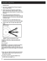
Page 17: ...to scribed mark Y dimension Cut off outer shield at the mark Cut same amount off the outer shaft Y1 dimension 7 Remove all burrs 8 Continue with Check Driveline Maximum Length CHECK DRIVELINE MAXIMUM...

Page 18: ...set tractor 3 point lift height to keep driveline from exceeding 25 up MODIFYING PTO driveline shield 7 Start tractor and raise Rotary Tiller just enough to remove support blocks 8 Slowly engage tract...

Page 19: ...until the tractor has been shut down and the tiller tines have completely stopped IMPORTANT Never travel at a fast ground speed while using the tiller as this could damage it Never attempt to turn th...

Page 20: ...de hex shaft out of side gearbox first and then remove it from main gearbox 10 Remove fill plug from top of gear box 11 Remove flat plug from bottom of gear box Switch the fill plug from top of gearbo...

Page 21: ...w turn and till with reverse direction 16 Flip gearbox over and re insert into frame 13 Using snap ring pliers carefully remove snap ring 14 Remove washer from hex shaft hole as well 15 Put washer and...

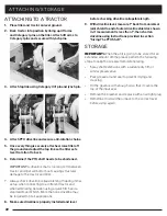
Page 22: ...HING TO A TRACTOR 1 Place tiller and tractor on level ground 2 Back tractor into position by lining up lift arms and Category I pins on the tiller Attach lift arms to Category I pins and secure with l...

Page 23: ...V Rotor Shaft Speed 211 rpm 540 rpm PTO 211 rpm 540 rpm PTO 211 rpm 540 rpm PTO Skid shoes adjustable 0 4 1 4 2 4 adjustable 0 4 1 4 2 4 adjustable 0 4 1 4 2 4 Top Gearbox construction Cast Iron Housi...

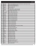
Page 24: ...9000172 Rear Guard Steel Hinge w Hardware black 4 4a 9000173 Rear Guard Steel Hinge w Hardware black 5 4b 9000174 Rear Guard Steel Hinge w Hardware black 6 4c 9000175 Rear Guard Steel Hinge w Hardwar...

Page 25: ...Guard Assembly black 6 16c 9000201 Rear Guard Assembly black 7 17 9000202 Frame Assembly black 4 17a 9000203 Frame Assembly black 5 17b 9000204 Frame Assembly black 6 17c 9000185 Frame Assembly black...

Page 26: ...8 S 406 Retaining Ring 9 S 124 Bearing 10 H C0144 Gasket rectangle 11 H C0142 Gasket 12 S 403 Retaining Ring 13 S 123 Bearing 14 H C0125 Input Shaft 15 S 404 72mm retaining ring 16 S 102 6207 bearing...

Page 27: ...earing 9 S 406 Retaining Ring 10 S 126 Bearing 11 S 133 Bearing 12 S 410 Retaining Ring 13 S 412 Retaining Ring Item Part Description 14 H C0253 Washer 15 H C0216 Washer 16 H C0255 Washer 17 2000019 M...

Page 28: ...16 x 1 Hex Head Bolt Plated 4 3 8 Split Lock Washer 4 3 8 Grd 5 Hex Nut 4 1 4 20 x 3 4 Hex Bolt 4 1 4 Screw Pin Chain Shackle 1 1 4 Flat Washer 4 1 4 Plated Proof Coil Chain X 19 1 1 4 Proof Coil Cha...

Page 29: ...16 5 8 11 UNC 97 131 150 203 212 287 15 16 5 8 18 UNF 110 149 170 230 240 325 1 1 8 3 4 10 UNC 144 195 266 360 376 509 1 1 8 3 4 16 UNF 192 260 297 406 420 569 1 5 16 7 8 9 UNC 166 225 430 583 606 82...

Page 30: ...mal gearbox noise Low oil level worn gears gearbox bearings Check oil level replace gears gearbox replace bearings Tiller makes intermittent abnormal noise Tines are loose gearbox has damaged tooth de...

Page 31: ...s limited warranty is extended solely to the original purchaser of the product Should the original purchaser sell or otherwise transfer this product to a third party this warranty does not transfer to...

Page 32: ...ess for a particular purpose No other express warranty whether written or oral given by any person or entity including a retailer with respect to any product shall bind manufacturer Manufacturer s exc...

Page 33: ...33 NOTES...

Page 34: ...34 NOTES...

Page 35: ...35 NOTES...

Page 36: ...4000047 REV 1 022321 P O BOX 10 10739 S HWY 127 DUNNVILLE KY 42528 1 800 REDGATE TARTERUSA COM For more information about Proposition 65 please visit https www p65warnings ca gov...

Reviews: