Connections and settings
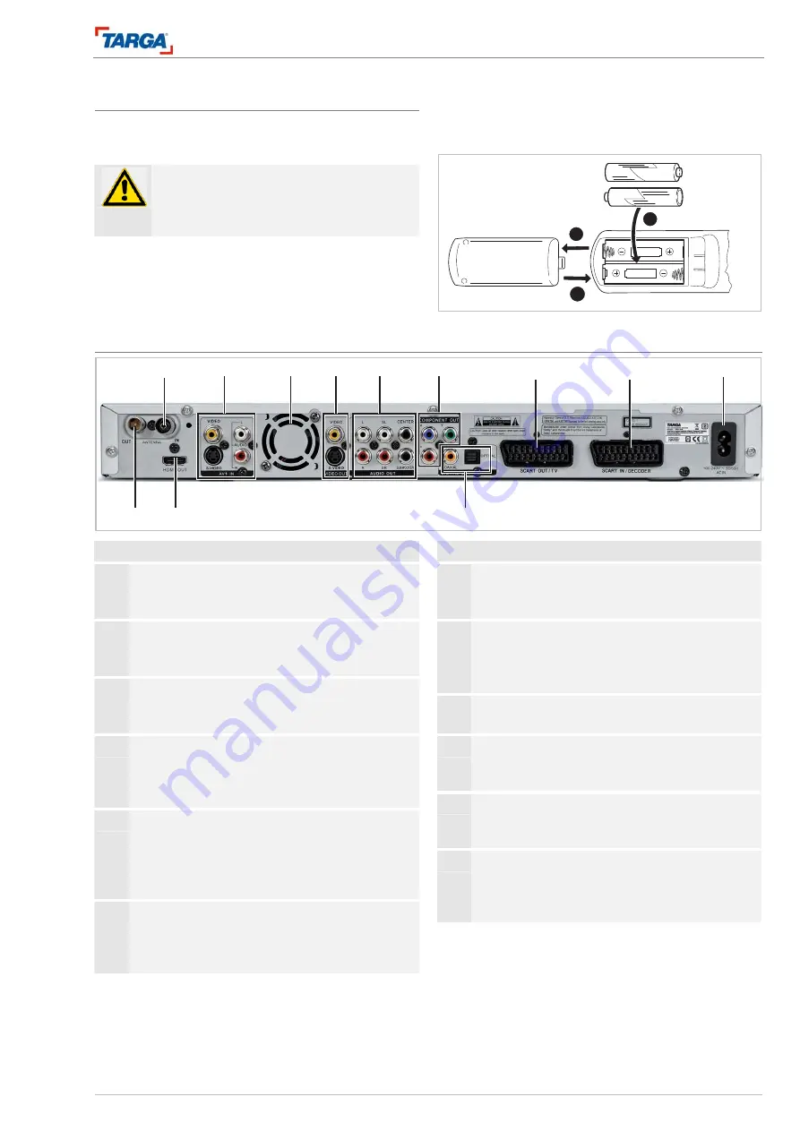
Connections on the back of the unit
DRH-5700x
15
Using the remote control
Direct the remote control at the remote control sensor.
Inserting batteries in the remote control
Important!
Do not use old and new batteries or different
types of battery (standard, alkaline, etc.) to-
gether.
Remove the battery compartment cover on the back
of the remote control and insert two LR03 batteries
(size AAA) with the correct polarity.
See the diagram inside the battery compartment.
2
1
3
Connections and settings
Connections on the back of the unit
16
17
18
19
20
21
22
23
24
25
26
27
No. Designation
16 ANTENNA IN
For connecting a television antenna or cable te-
levision.
17 AV1 IN (picture and sound)
S-Video 1, CVBS 1
AUDIO signal input.
18 Fan
The fan provides sufficient ventilation inside the
housing. Never cover the ventilation openings.
19 VIDEO OUT (picture)
VIDEO or S-VIDEO signal output (analogue) for
connecting to an S-video cable or video cable
(cinch).
20 AUDIO OUT (sound)
5.1 channel surround sound: signal output parallel
to the A/V amplifier or active speaker system, six
coaxial cinch cables (L, R, SL, SR, CENTER,
SUBWOOFER).
21 COMPONENT OUT (picture)
Analogue component signal output, YPbPr, for
connecting televisions, displays via component
video cable.
No. Designation
22 SCART OUT / TV (picture and sound)
Analogue picture and sound output for connect-
ing a television.
23 SCART IN / DECODER (picture and sound)
Analogue picture and sound input for connecting
decoders, satellite receivers, video recorders,
etc.
24 AC IN (AC 230 V, 50 Hz)
Socket for power supply cable.
25 DIGITAL OUT (sound)
Digital optical sound output (fibre optic cable),
digital coaxial sound output (cinch cable).
26 HDMI OUT (picture and sound)
Digital picture and sound output for connecting
televisions, displays with an HDMI cable.
27 ANTENNA OUT
For connecting to the antenna input on the tele-
vision. The antenna signal at socket 16 is redi-
rected to the television via this socket.


