


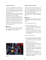

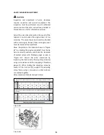
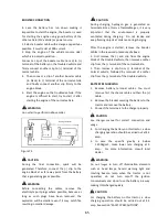


SAFETY START CONTROL
The Tractor is equipped with a safety starter switch
to protect the operator and the persons around
him from potential dangers caused the abrupt
starting of the engine with gear applied or an
implement mounted.
This safety system prevents tractor from starting
before shuttle lever and PTO shift lever are placed
in NEUTRAL and the clutch is depressed.
To make sure if this function works properly, try
starting the tractor when PTO shift lever and/or
shuttle lever is engaged and the clutch pedal is
depressed or not. If the tractor does not start, it
means that these functions are working properly.
If the tractor starts when even one of the
conditions above is not met, take it to your dealer
as soon possible for repair.
When checking the function, make sure that the
main shift lever is in neutral and hand clutch lever
is not engaged (lower) for your safety.
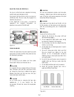
HYDRAULIC CONTROL ADJUSTMENT
Operation of the hydraulic control systems of the
tractor is described in sections “HYDRAULIC LIFT”
and “3 POINT LINKAGE SYSTEM”. In order that
controls are functioning properly, the mechanical
adjustments must be performed fully.
If any problem occurs relating to the operation of
the hydraulic system, check the adjustments
below.
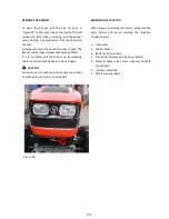
When performing these adjustments, mount a 150-
kg weight to the links in order to see and evaluete
the impact.
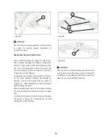
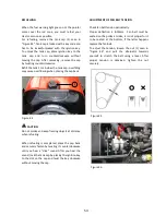
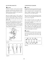
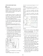
In order to adjust position control:
1.
Release the hydraulic valve lock.
2.
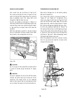
If the arms do not go up when the position
control lever is pushed forward, tighten the nut
(1) seen in “Figure 56”.
3.
If the arms are moving when the position
control lever is applied lower but you want it to
move at a higher position, loosen the nut (no1)
seen in "Figure 56".
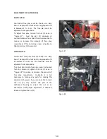
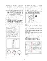
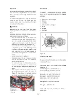
In order to adjust depth control:
1.
Move the weight on the lifting arms upward
using position control lever but do not adjust it
to the highest level; try to keep it at a medium
level.
2.
Release the hydraulic valve lock.
3.
Stretch the precision string (3) seen in "Figure
56" by using the middle arm to apply force to
the front side of the tractor.
4.
If the mounted weight does not move despite
stretching the string, tighten the nut (2) seen in
"Figure 56" and continue to tighten the nut
until the weight moves.
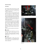
5.
Loosen the nut (2) seen in “Figure 56”, if the
mounted weight is moving too much when a
little amount of force is applied, or if the
weights are moving when the force is stopped
instead the force is applied.
CAUTION
WARNING
Figure 56
1
3
2
58
Summary of Contents for 850
Page 1: ......
Page 2: ......
Page 7: ......
Page 12: ......
Page 24: ...12 ...
Page 28: ...16 ...
Page 50: ...38 ...
Page 54: ...42 ...
Page 78: ...PROPER BATTERY SERVICE AND TIPS FOR SAFETY Table 7 66 ...
Page 86: ...74 ...
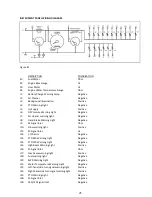
Page 87: ...SECTION 7 TECHNICAL SPECIFICATIONS Figure 83 Table 8 Technical Specs 75 ...
Page 89: ...Figure 84 Table 11 Turning Radius 77 ...
Page 94: ...82 ...
Page 100: ...88 ...
Page 101: ......


