2
PORT-O-SLITTER
®
SETUP AND OPERATION
1. ASSEMBLY OF YOUR PORT-O-SLITTER
Remove the contents of the PARTS BAG, which should include 2 “T” WRENCHES and the CRANK HANDLE
ASSEMBLY. Install the HANDLE and tighten the SET SCREW against the “flat” on the SHAFT. Make sure that the
HANDLE turns freely without interference.
2. PORT-O-SLITTER OPERATION—SLITTING
A. Loosen the SET SCREWS on the LOWER SLITTING KNIFE and slide the KNIFE
into the cutting position by aligning the cutting edge of the KNIFE with the desired
measurement on the TAPE MEASURE. Tighten the SET SCREW. IMPORTANT:
Tighten all SET SCREWS against the FLATS of the SHAFTS only. Carefully
slide the upper SLITTING KNIFE against the lower KNIFE and tighten that SET
SCREW securely using the “T” WRENCH provided. To avoid damaging the SLIT-
TING KNIVES, do not “BANG” the KNIVES together when adjusting them. To make
more than one simultaneous cut repeat this procedure with the other KNIVES. If only one cut is being made, move
the remaining KNIVES at least three inches apart to avoid cutting or marking your material.
B. Next, adjust the right and left COIL GUIDE BARS. In most cases, set the right COIL GUIDE BAR at zero on the tape
measure, place the right edge of the material into the slot, then draw the left COIL GUIDE BAR to the left edge of the
material and tighten the knurled knobs. Periodically check COIL GUIDE BARS for squareness.
C. Now push the material into the SLITTER while turning the CRANK HANDLE counterclockwise.
NEVER PLACE HANDS OR CLOTHING NEAR KNIVES WHILE IN OPERATION.
D. For maximum performance during the slitting operation, keep the material flat over the front RECEIVER ROLLER
as the material exits.
E. When slitting harder and thicker materials, or if twisting of the material occurs, separate the KNIVES a few thou-
sandths of an inch to provide a better cut.
F. When slitting close to one edge of wide material, it may be helpful to lightly hold the material down on the COIL
TABLE surface in order to keep it from bowing upwards.
3. PORT-O-SLITTER OPERATION—RIB FORMING
A. To form “RIBS” for stiffening and decoration, set the KNIVES approximately 1/8" apart. Experiment to achieve
different effects. Refer to section 4 below for more information.
4. KNIFE CONFIGURATION AND SET-UP
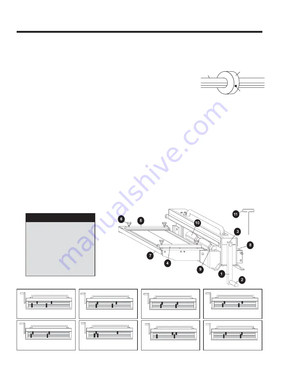
• Standard KNIFE configurations which can be used are shown below.
KNIFE CONFIGURATION FROM FACTORY
TWO SINGLE “RIBS”
FORMED SIMULTANEOUSLY
CONFIGURATION FOR 1 SLIT
ONE DOUBLE “RIB” FORMED DOWN
TWO SLITS SIMULTANEOUSLY
ONE DOUBLE “RIB” FORMED UP
ONE SINGLE “RIB” FORM
ONE SLIT & ONE SINGLE “RIB”
FORMED SIMULTANEOUSLY
STANDARD KNIFE CONFIGURATIONS
KNIFE
SHAFT
SET SCREW
QUICK GUIDE
1. CRANK HANDLE ASSEMBLY
2. CRANK HANDLE
3. CRANK HANDLE SET SCREW
4. RIGHT COIL GUIDE BAR
5. LEFT COIL GUIDE BAR
6. KNURLED KNOB
7. COIL TABLE
8. RECEIVER ROLLER
9. KNIFE
10. SHAFT
11. “T” HEX WRENCH (1 OF 2)


