082406-40
TC36.CSTE 9
MAESTRO CONTROL SYSTEM
The gas control system is located on the right hand side of
the fi rebox behind an access panel and the decorative brick
panel. The fi replace is operated via a wall switch that can be
located up to 25 ft away from the fi replace and also by a hand
held remote control unit.
SERVICE CONNECTIONS
1) Locate the fi replace in the desired location.
2)
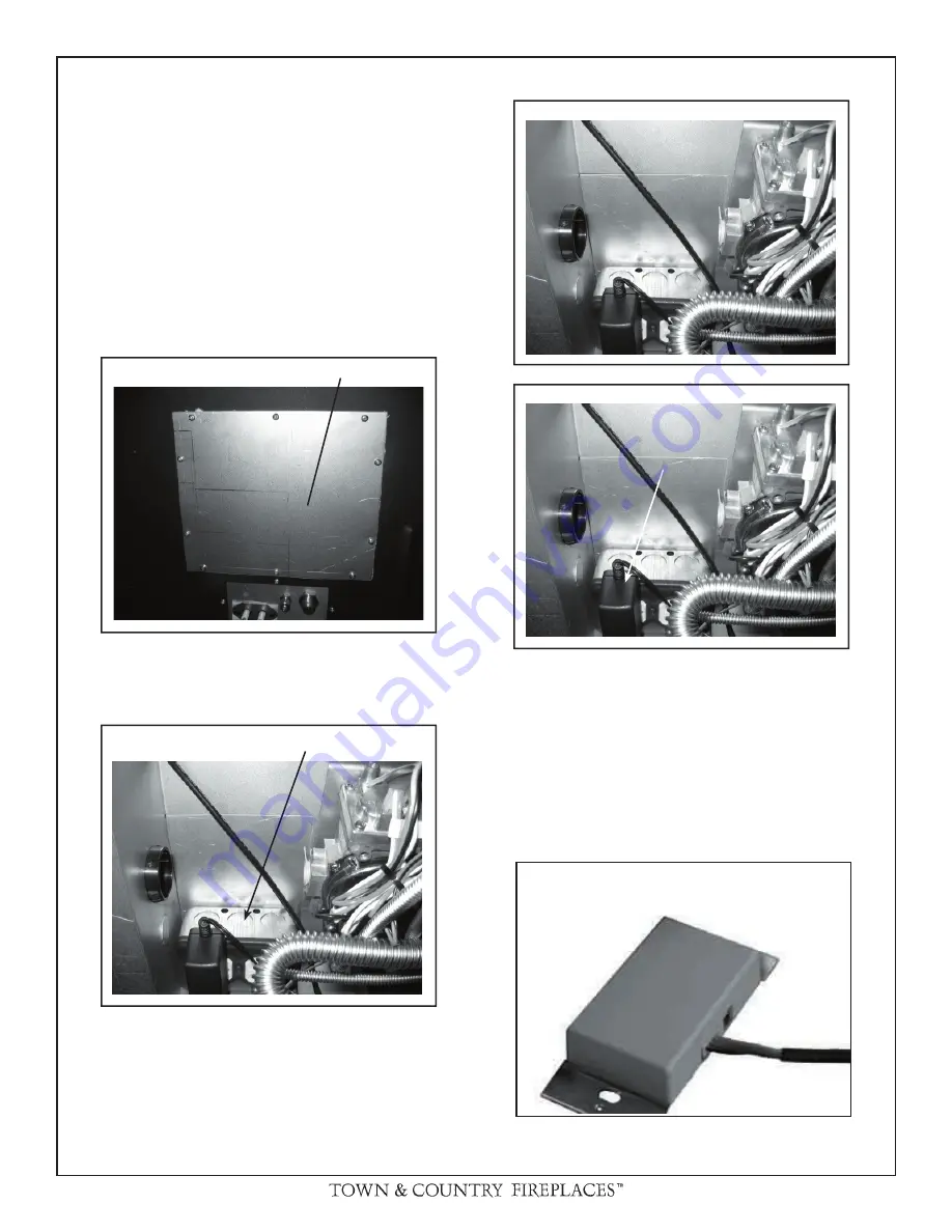
Remove access panel from right hand side of the fi rebox
(Fig. #10)
3)
Connect a 110v AC electrical supply to the outlet installed
inside the control box (Fig. #11)
4) Connect the gas supply to the valve (Fig. #12)
5) Plug the A/C adaptor into the outlet (Fig. #13)
6)
Attach the electrical box for the supplied wall control to the
framing in the desired location (up to 25ft away).
7)
Route the control cable as required to the wall control
electrical box.
8) Attach the control cable to the wall control. (Fig. #14)
9)
Insert the 4 supplied “AA” batteries into the battery pack
and connect to wall control. (Fig. #15)
10) Fasten the wall switch to the electrical box.
11) Fasten the faceplate to switch
12) Remove the burner from the packaging and install as per
its installation instructions.
Fig. # 10
Fig. # 11
Fig. # 12
Fig. # 13
Fig. # 14
ACCESS PANEL
OUTLET
AC ADAPTER
AC ADAPTER
Summary of Contents for TC36ST
Page 38: ...38 TC36 CSTE 082406 40 NOTES...
Page 39: ...082406 40 TC36 CSTE 39 NOTES...


