background image

GB-5

*
%

Assembly procedures

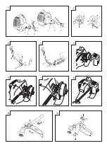
Drive shaft to engine (Fig. 1)

Loosen tube locking bolt (1) about ten turns so that the bolt point 

will not obstruct drive shaft tube to be inserted. When inserting 

drive shaft tube, hold the tube locking bolt outward preventing 

inside fitting from obstructing as well.

Insert the drive shaft into the clutch case of the engine properly 

until the marked position (2) on the drive shaft tube meets the 

clutch case.

NOTE!

When it is hard to insert drive shaft up to the marked position on 

the drive shaft tube, turn drive shaft by the cutter mounting end 

clockwise or counter-clockwise. Tighten tube locking bolt lining up 

the hole in the shaft tube.

Then tighten clamp bolt securely (3).

Installation of handle

 WARNING!

When you use steel/rigid blade on straight shaft trimmers or 

brush cutters, always use barrier bar (2) and shoulder harness 

with the loop handle. (Fig. 2)

Attach the handle to the drive shaft tube with the angle towards the 

engine.

Adjust the location to the most comfortable position before 

operation.

NOTE!

If your unit has handle location label on drive shaft tube, follow 

indication.

Remove the handle bracket (1) from the assembly. (Fig. 3)

Place the handles and attach the handle bracket with four bolts 

lightly. Adjust to appropriate position. Then fix it firmly with the 

bolts.

Put stop cords (3) and throttle wire (1) through protective tube (2), 

then unhook the hip pad. (Fig. 4)

Throttle wire / stop cord

Remove air cleaner cover. (Fig. 5) 

Connect stop cords (1). (Fig. 6)

Connect throttle wire end (1) to carburetor (2). (Fig. 7)

Cover throttle wire and stop cords together with protective tube 

provided up to air cleaner cover. (Fig. 8)

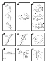
Installation of blade guard (Fig. 9, 10, 11)

NOTE! 

The guard bracket may come already mounted to the gear case on 

some models.

Install the blade guard and the bracket spacers (1) (If so equipped) 

on drive shaft tube against angle transmission. Tighten the guard 

bracket firmly so that the blade guard does not swing or move 

down during operation.

Install the blade guard to the guard bracket, which also secures the 

guard to the gear case using the two guard mounting screws.

CAUTION!

Some blade guards are equipped with sharp line limiters. Be 

careful with handling it.

NOTE! (Fig. 11)

When using Tanaka aluminum head (CH-100 or CH-300) on your 

unit, the sharp line limiter (2) (If so equipped) which is included in 

the tool bag, should be securely fastened to the blade guard using 

the bolt shown (3).

When using a trimmer head with two piece type blade guard, attach 

the guard extension to the blade guard. (Fig. 12)

NOTE!

When attaching the guard extension to the blade guard, the sharp 

line limiter must be removed from the blade guard, (if so installed).

NOTE!

If your unit has guard location label on drive shaft tube, follow the 

indication.

NOTE!

To remove the guard extension, refer to the drawings. Wear gloves 

as the extension has a sharp line limiter, then push the four square 

tabs on the guard one by one in order. (Fig. 13)

Installation of cutting blade (Fig. 14, 15)

(If so equipped)

When installing a cutting blade, make sure that there are no cracks 

or any damage in it and that the cutting edges are facing the 

correct direction.

NOTE!

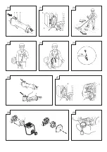
When installing cutter holder cap (1), be sure to set concave side 

upward.

Insert the allen wrench (2) into the hole of the angle transmission 

in order to lock the cutter holder (3). Please note that the cutter 

fixing bolt or nut (4) has left-handed threads, (clockwise to loosen/

counter-clockwise to tighten). Tighten the fixing bolt or nut with the 

box wrench.

NOTE!

If your unit is of a nut securing type and equipped with a cotter 

pin, the blade must be retained with a new cotter pin (5) each time 

installed. (Fig. 16)

CAUTION!

Before operation, make sure the blade has been properly installed.

CAUTION!

If your unit is equipped with protection cover under a cutting blade, 

check it for wear or cracks before operation. If any damage or wear 

is found, replace it, as it is an article of consumption.

Installation of semi-auto cutting head

NOTE!

For installation see your Owner's manual, provided with the cutting 

head.

 WARNING!

For outstanding performance and reliability, always use Tanaka 

nylon cutting line. Never use wire or other materials that could 

become a dangerous projectile.

Installation of the BRAIN cutting head

NOTE!

For installation see your BRAIN Owner's manual, provided with the 

BRAIN cutting head.

Summary of Contents for TBC-290 series

Page 1: ...ttere in funzione questa apparecchiatura Lees de handleiding zorgvuldig door voordat u de machine bedient Antes de utilizar esta m quina lea cuidadosamente el manual Leia o manual atentamente antes de...

Page 2: ......

Page 3: ......

Page 4: ...FP FP...

Page 5: ...P...

Page 6: ...30 31 5 PP PP 32...

Page 7: ...occur causing the entire unit and operator to be thrust violently This reaction is called BLADE THRUST As a result the operator may lose control of the unit which may cause serious or fatal injury Bl...

Page 8: ...apply to your unit 1 Fuel cap 2 Throttle trigger 3 Starter handle 4 Blade guard 5 Cutting attachment 6 Drive shaft tube 7 Handle bar 8 Suspension eyelet 9 Ignition switch 10 Harness 11 Throttle lock...

Page 9: ...before starting engine Stop engine before removing fuel cap Empty the fuel tank before storing the unit machine It is recommended that the fuel be emptied after each use If fuel is left in the tank s...

Page 10: ...e 6 3 5 1 2 9 3 4 5 7 3 8 3 0 3 1 1 4 Equivalent Rear handle Right handle 3 4 5 6 3 3 4 4 6 3 4 3 3 0 4 2 1 6 Uncertainty 1 5 1 5 1 5 1 5 1 5 1 5 1 5 1 5 1 5 Idling Front handle Left handle 1 9 1 6 2...

Page 11: ...ng the two guard mounting screws CAUTION Some blade guards are equipped with sharp line limiters Be careful with handling it NOTE Fig 11 When using Tanaka aluminum head CH 100 or CH 300 on your unit t...

Page 12: ...after refueling Before fueling clean the tank cap area carefully to ensure that no dirt falls into the tank Make sure that the fuel is well mixed by shaking the container before fueling Starting Fig...

Page 13: ...Standard Idle rpm is 2 800 3 200 min 1 NOTE TBC 290 D S TBC 340 D DS The standard openings returns of H screw from lightly seated position is as follows If so equipped TBC 290 D S TBC 340 D DS H SCRE...

Page 14: ...ase of a 3 or 4 tooth blade 1 it can be used on either side Use correct blade for the type of work When replacing blade use appropriate tools When cutting edges become dull re sharpen or le as shown i...

Page 15: ...fornien als Erreger von Krebs Geburtsfehlern undanderen Fortp anzungssch den angesehen werden Symbolbedeutungen HINWEIS Nicht alle Ger te sind mit diesen Symbolen versehen Symbole WARNUNG Die folgende...

Page 16: ...rt 11 Gashebelsperre 12 Sicherheitsgasgriff 13 Chokehebel 14 Motor 15 Winkelgetriebe 16 Sch ftungsgeh use 17 Kombinierter Steckschl ssel 18 Bedienungsanleitung 10 10 10 Teilebezeichnungen Da dieses Ha...

Page 17: ...rs das Ger t mindestens 3 m von der Kraftstoff einf llstelle entfernen Vor dem Abnehmen des Tankdeckels den Motor ausschalten Vor der Einlagerung des Ger ts den Kraftstoff tank leeren Es wird empfohle...

Page 18: ...ldruckpegel LpA dB A ISO 22868 quivalen 95 0 93 8 98 2 94 7 94 7 98 2 96 8 93 4 96 8 Unsicherheit 3 3 3 3 3 3 3 3 3 Gemessener Schallpegel LwA dB A ISO 22868 quivalen 110 107 110 107 107 110 109 106 1...

Page 19: ...ze sind mit scharfen Messern unter der Abdeckung ausger stet Behandeln Sie diese sorgf ltig HINWEIS Abb 11 Bei Verwendung eines Tanaka Aluminiumkopfes CH 100 bzw CH 300 sollte der im Werkzeugbeutel en...

Page 20: ...auf etwaige Treibstof ecks Beim Auftanken auf Reinlichkeit achten Um den Tankdeckel herum sauber abwischen Verunreinigungen im Tank k nnen zu Betriebsst rungen f hren Vor dem Auftanken den Kraftstoff...

Page 21: ...laufdrehzahl ist 2 800 3 200 min 1 HINWEIS TBC 290 D S TBC 340 D DS Der normale ffnungsgrad R ckw rtsdre hungen f r eine H Schraube von der leicht angezogenen Stellung aus ist wie folgt Falls vorhande...

Page 22: ...ssend zur Art der beabsichtigten Arbeit w hlen Zum Messerwechsel stets das passende Werkzeug verwenden Sobald die Schneidkanten stumpf sind gem der Abbildung sch rfen oder feilen Falsches Sch rfen kan...

Page 23: ...ouvelle machine Lisez attentivement le manuel d utilisation V ri ez que l quipement de coupe est mont et r gl correctement D marrez la machine et v ri ez le r glage du carburateur Voir la section ENTR...

Page 24: ...hage 9 Interrupteur marche arr t 10 Harnais 11 Blocage de la commande des gaz 12 Levier de s curit 13 Levier de starter 14 Moteur 15 Bo tier de renvoi d angle 16 Bo tier de raccordement 17 Cl douille...

Page 25: ...d visser les bouchons des r servoirs de carburant ou d huile Vidangez le r servoir de carburant avant de ranger la machine Cette op ration est recommand e apr s chaque utilisation Si le r servoir n es...

Page 26: ...Bougie d allumage CHAMPION RCJ6Y ou quivalent CHAMPION RCJ6Y or CJ6Y ou quivalent CHAMPION RCJ6Y or CJ6Y ou quivalent Ralenti min 1 3 000 3 000 3 000 Vitesse maximum recommand e min 1 11 000 11 000 1...

Page 27: ...si le garde au cas d engrenage utilisant le deux garde monte des vis REMARQUE Quelques carters de protection sont munies de couteaux tranchants pour limiter la longueur du l Prenez garde lorsque vous...

Page 28: ...ngers ne p n trent dans le r servoir Les salet s qui se trouveraient dans le r servoir risquant d occasionner des troubles de fonctionnement Veillez ce que le m lange soit bien homog ne en agitant int...

Page 29: ...ssionnaire Tanaka REMARQUE Le nombre normal de tours par minute au ralenti est de 2 800 3 200 tr mn REMARQUE TBC 290 D S TBC 340 D DS Le r glage dans le sens inverse des aiguilles d une montre standar...

Page 30: ...ex cuter Lors du remplacement de la lame employer les outils appropri s Quand les bords tranchants deviennent mouss s les aiguiser de nouveau ou les limer comme indiqu sur la gure L aiguisage incorrec...

Page 31: ...i comprenderne il signi cato prima dell uso Leggere comprendere a fondo e osservare tutte le avvertenze e le istruzioni riportate nelle presenti istruzioni per l uso e sull unit importante leggere com...

Page 32: ...10 Cinghia e bretelle 11 Pulsante di bloccaggio acceleratore 12 Leva fermo acceleratore 13 Comando dell aria 14 Motore 15 Coppia conica 16 Manicotto di giuntura 17 Chiave a tubo combinata 18 Istruzio...

Page 33: ...rimuovere il tappo del serbatoio del carburante Prima di conservare l unit macchina se ne deve svuotare completamente il serbatoio del carburante Questa precauzione deve essere adottata dopo ogni uso...

Page 34: ...ivalente 95 0 93 8 98 2 94 7 94 7 98 2 96 8 93 4 96 8 Incertezza 3 3 3 3 3 3 3 3 3 Livello potenza sonora misurata LwA dB A ISO 22868 Equivalente 110 107 110 107 107 110 109 106 109 Livello potenza so...

Page 35: ...lli e non si muova durante il lavoro Applicate la protezione lama alla relativa staffa che ssa la protezione anche alla coppia conica utilizzando le due viti di ssaggio IMPORTANTE Alcuni coprilama son...

Page 36: ...presenza di perdite Prima del rifornimento pulire la zona intorno al tappo con cautela per evitare la penetrazione di sporco nel serbatoio Controllare che la miscela sia ben mescolata agitando il rec...

Page 37: ...ure i ritorni standard della vite H dalla posizione di tutto chiuso sono le seguenti Se la macchina ne fornita TBC 290 D S TBC 340 D DS Vite H 1 NOTA Alcuni modelli venduti in zone con norme rigorose...

Page 38: ...sostituite la lama usate attrezzi appropriati Quando i bordi taglienti perdono il lo riaf lateli o limateli come illustrato in gura Un af latura eseguita non correttamente pu causare eccessive vibrazi...

Page 39: ...en met ernstig of zelfs fataal letsel tot gevolg Messlingering komt meestal voor op plaatsen waar het te snijden materiaal moeilijk te zien is Gebruik geen metalen onbuigzame mesbladen als dit symbool...

Page 40: ...gereedschap 6 Aandrijfasbehuizing 7 Handgreep 8 Oog voor draaggordel 9 Ontstekings schakelaar 10 Draaggordel 11 Gashendel vergrendeling 12 Veiligheidshendel 13 Choke hendel 14 Motor 15 Hoekoverbrengin...

Page 41: ...aats waar u getankt heeft vandaan voor u de motor start Stop de motor voor u de brandstofdop verwijdert Maak de brandstoftank helemaal leeg voor u de machine opbergt We raden u aan de tank elke keer n...

Page 42: ...7 98 2 96 8 93 4 96 8 Onzekerheid 3 3 3 3 3 3 3 3 3 Gemeten geluidsdrukniveau LwA dB A ISO 22868 Gelijkwaardig 110 107 110 107 107 110 109 106 109 Gegarandeerd geluidsdrukniveau LwA dB A 2000 14 EC Ma...

Page 43: ...pe kantlijnbegrenzingen Ga hier voorzichtig mee om ATTENTIE Afb 11 Als u een Tanaka aluminium kop CH 100 of CH 300 voor uw machine gebruikt moet de scherpe kantlijnbegrenzing 2 Indien aanwezig die zic...

Page 44: ...kt vandaan alvorens u de motor start Was eventueel op uw kleding gemorste brandstof er onmiddellijk uit met zeep of een wasmiddel Controleer of er ergens brandstof lekt na het tanken Maak de tankdop z...

Page 45: ...DS H SCHROEF 1 TIP Sommige modellen die in gebieden worden verkocht met strenge milieuwetgeving hebben geen mogelijkheid om de carburateur op lage en hoge snelheid af te stellen Dit omdat daardoor de...

Page 46: ...van een mesblad moet de originele vorm van de radius aan de basis van de tand behouden worden om barsten te voorkomen Onderhoudsschema Hier vindt u nog enkele algemene onderhoudsinstructies Neem voor...

Page 47: ...anque el aparato y compruebe el ajuste del carburador Consulte MANTENIMIENTO Signi cado de los s mbolos NOTA Algunos aparatos no est n provistos de ellos S mbolos ADVERTENCIA A continuaci n se muestra...

Page 48: ...de ignici n 10 Arn s 11 Bloqueo del acelerador 12 Palanca de tope del acelerador 13 Estrangulador 14 Motor 15 Transmisi n angular 16 Caia de acoplamiento 17 Llave combinada de cubo 18 Instrucciones de...

Page 49: ...nga el motor antes de quitar la tapa del dep sito de combustible Vac e el dep sito de combustible antes de guardar el aparato Se recomienda vaciar el dep sito de combustible cada vez que termine de ut...

Page 50: ...1 4 Equivalente Asidero trasero derecho 3 4 5 6 3 3 4 4 6 3 4 3 3 0 4 2 1 6 Incertidumbre 1 5 1 5 1 5 1 5 1 5 1 5 1 5 1 5 1 5 Ralent Asidero delantero izquierdo 1 9 1 6 2 4 2 9 1 3 1 1 2 1 1 2 1 3 Ra...

Page 51: ...MPORTANTE Algunos protectores de cuchilla est n equipados con limitadores de linea a lados T ngase cuidado al manejarlo NOTA Fig 11 Cuando se usa una cabeza de aluminio de Tanaka CH 100 o CH 300 en su...

Page 52: ...spu s del llenado Antes de repostar limpiar cuidadosamente el rea del tap n del tanque para asequrar que no entre suciedad en el dep sito Asegurarse de que el combustible est bien mezclado agitando bi...

Page 53: ...TA Algunos modelan vendido en reas con regulaciones estrictas de emisi n de escape no tiene los ajustes altos y bajos de carburador de velocidad Tales ajustes pueden permitir el motor para ser operado...

Page 54: ...se seg n lo indicado en la gura La a ladura incorrecta puede causar vibraciones excesivas Desc rtense las hojas que se han hecho encorvadas alabeadas grietadas fracturadas o da adas de cualquier maner...

Page 55: ...parelho importante que leia compreenda integralmente e respeite as seguintes precau es e advert ncias de seguran a O uso do aparelho de forma incorrecta ou sem os cuidados necess rios pode causar les...

Page 56: ...9 Interruptor de igni o 10 Cinto 11 Engate do acelerador 12 Trav o de acelerador 13 Alavanca do ar 14 Motor 15 Transmiss o em ngulo 16 Mala articulada 17 Ferramenta universal 18 Instru es de uso 10 1...

Page 57: ...dep sito de combust vel Esvazie o dep sito de combust vel antes de guardar o aparelho recomend vel esvaziar o dep sito de combust vel ap s cada uso No caso de deixar o combust vel no dep sito guarde o...

Page 58: ...te 95 0 93 8 98 2 94 7 94 7 98 2 96 8 93 4 96 8 Incerteza 3 3 3 3 3 3 3 3 3 N vel de pot ncia sonora medida LwA dB A ISO 22868 Equivalente 110 107 110 107 107 110 109 106 109 N vel de pot ncia sonora...

Page 59: ...a o painel caixa de transmiss o usando os 2 parafusos CUIDADO Alguns revestimentos de l mina s o equipados com bordos cortantes Tenha cuidado ao manusear com eles ANOTA O Fig 11 Se usar uma cabe a de...

Page 60: ...gua e sab o Controle a unidade por eventuais fugas de gasolina depois de abastecer o dep sito Antes de abastecer com gasolina limpe a zona do tamp o do dep sito com cuidado Assim evita que a sujeira e...

Page 61: ...es com severas normas de controlo de emiss es n o possuem o ajuste de alta e baixa velocidade do carburador Estes ajustes permitem que o motor possa operar fora dos limites de emiss es Nestes modelos...

Page 62: ...ma neira devem ser deitadas ao lixo ANOTA O Ao a ar a l mina importante manter a forma genu na do raio na base da dentadura para evitar a ssuras Plano de manuten o Mais abaixo vai encontrar algumas in...

Page 63: ...GR 1 5 PLQ 15 m 2 3 4 5 6 7...

Page 64: ...GR 2 1 2 3 4 5 6 7 8 9 10 11 12 13 14 15 16 17 18 O 10 10 10...

Page 65: ...GR 3 5 96 7DQDND 7DQDND...

Page 66: ...BC 290 S TBC 290D TBC 340 TBC 340D 340DS TBC 340PF TBC 340PFD 340PFDS FP PO FX LQ FX LQ FX LQ 03 21 5 03 21 5 RU 03 21 5 RU PLQ PLQ PLQ N FP PO R R R NJ OEV OEV OEV OEV OEV PP 7 7 7 7 S G 62 Z G 62 Z...

Page 67: ...GR 5 5 1 1 2 3 2 2 1 3 3 1 2 4 5 1 6 7 8 o 9 10 11 1 11 Tanaka CH 100 CH 300 2 3 12 13 14 15 1 2 3 4 5 16 7DQDND BRAIN BRAIN BRAIN...

Page 68: ...RAIN Tanaka Tanaka CH 100 17cm 17 18 89 25 1 50 1 Tanaka 50 1 JASO FC GRADE OIL ISO EGC GRADE BIA TCW 10 W130 PO 1 3 10 19 20 21 1 1 19 20 4 21 2 3 CLOSED 5 21 4 5 RUN 2 5 6 2 3 22 23 24 25 6500 rpm 1...

Page 69: ...GR 7 5 26 27 Tanaka 2 800 3 200 min 1 TBC 290 D S TBC 340 D DS H TBC 290 D S TBC 340 D DS 1 90 Tanaka 28 1 1 29 30...

Page 70: ...GR 8 0 6 024 100 31 50 32 Tanaka 25 4 mm Tanaka 3 4 7DQDND...

Page 71: ...0 02...

Page 72: ...ultare le speci che del capitolo Il Responsabile delle Norme Europee di Hitachi Koki Ltd autorizzato a compilare la scheda tecnica Questa dichiarazione applicabile ai prodotti cui sono applicati imarc...

Reviews: