background image


Assembly instructions 


Product description 


10 / 35 

Rotary indexer TMF 

Version 1.0 


TMF2000 

Roll star / output flange Ø [mm] 

560 

Overall height (roll star mounting surface) [mm] 

285 

Internal diameter Ø [mm] 

190 

Internal transmission ratio [i] 

14 

Indexing accuracy in angular seconds [ " ] 

Length 

 Width 

 Height [mm] 

688.5 

 877 

 285 

Rotary indexer without drive approx. [kg] 

350 

Direction of rotation 

clockwise, counterclockwise, oscillating 

Installation position 

horizontal 


TMF3000 

Roll star / output flange Ø [mm] 

800 

Overall height (roll star mounting surface / output flange) [mm] 

330 

Internal diameter Ø [mm] 

280 

Internal transmission ratio [i] 

18 

Indexing accuracy in angular seconds [ " ] 

Length 

 Width 

 Height [mm] 

800 

 1028 

 330 

Rotary indexer without drive approx. [kg] 

480 

Direction of rotation 

clockwise, counterclockwise, oscillating 

Installation position 

horizontal 


Summary of Contents for TMF Series

Page 1: ...Rotary indexer TMF Version 1 0 2022 04 25 Assembly instructions ...

Page 2: ...s for incorporation into a complete machine 7 3 Product description 8 3 1 Intended use 8 3 2 Technical data 8 3 3 Product overview 13 4 Transport 16 4 1 Transport with slings 17 5 Assembly 18 5 1 Attachment positions 18 5 2 Drive attachment 18 5 3 Installation 24 6 Operation 25 6 1 Operating modes 25 7 Maintenance 26 7 1 Maintenance work 26 7 2 Lubricating 28 7 3 Replacing the cam follower 29 8 Tr...

Page 3: ...rovide users with all the information necessary for proper and safe installation of the rotary indexer in a complete machine 1 2 Contact information TAKTOMAT GmbH Rudolf Diesel Straße 14 86554 Pöttmes Tel 49 0 8253 9965 0 Fax 49 0 8253 9965 50 E mail info taktomat de Internet http www taktomat de 1 3 Product designation Product designation Rotary indexer Product type TMF ...

Page 4: ... be executed are numbered The results of individual action steps are indicated by a black arrow The overall result of an instruction is marked by a white arrow in a black circle Example Requirement 1 Instruction step 1 2 Instruction step 2 Result or response of system to step 2 3 Instruction step 3 Overall result of the instruction Enumerations Enumerations in no strict order are indicated as foll...

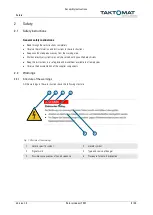
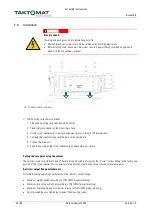
Page 5: ...systems may only be carried out by qualified electricians Keep the instructions in a safe place and make them available to all employees Observe the documentation of the supplier components 2 2 Warnings 2 2 1 Structure of the warnings All the warnings in these instructions have the following structure Fig 1 Structure of the warnings 1 Hazard specific symbol 2 Hazard symbol 3 Signal word 4 Type and...

Page 6: ...uation which may result in death or serious injury CAUTION Indicates a potentially hazardous situation which may result in minor or moderate injury NOTICE Indicates a potentially hazardous situation which may result in property and environmental damage The following symbols for dangers warnings mandatory requirements and prohibitions are used in this document General warning sign Warning Electrica...

Page 7: ...d personal protective equipment is indicated in the different chapters of these instructions 2 5 Requirements for incorporation into a complete machine The rotary indexer is partly completed machinery Operation of the rotary indexer is only permitted in a complete CE compliant machine or system The manufacturer of the complete machinery or system is responsible for integrating the rotary indexer i...

Page 8: ...ifications must be approved by TAKTOMAT The rotary indexer may only be operated within the defined operating parameters Use of the rotary indexer in the food sector is not permitted 3 2 Technical data 3 2 1 Operating conditions Application range indoors in enclosed spaces the installation room must be dry clean and low vibration Temperature range C 10 to 40 Relative humidity 40 to 70 Media do not ...

Page 9: ...otary indexer without drive approx kg 13 5 Direction of rotation clockwise counterclockwise oscillating Installation position horizontal overhead TMF1000 Roll star output flange Ø mm 438 Overall height roll star mounting surface mm 195 Internal diameter Ø mm 165 Internal transmission ratio i 14 Precision of absolute positioning in angular seconds 6 Precision of relative positioning in angular seco...

Page 10: ...ary indexer without drive approx kg 350 Direction of rotation clockwise counterclockwise oscillating Installation position horizontal TMF3000 Roll star output flange Ø mm 800 Overall height roll star mounting surface output flange mm 330 Internal diameter Ø mm 280 Internal transmission ratio i 18 Indexing accuracy in angular seconds 8 Length Width Height mm 800 1028 330 Rotary indexer without driv...

Page 11: ...55 Rotary indexer without drive approx kg 800 Direction of rotation clockwise counterclockwise oscillating Installation position horizontal TMF5000 Roll star output flange Ø mm 1360 Overall height roll star mounting surface output flange mm 405 Internal diameter Ø mm 750 Internal transmission ratio i 24 Indexing accuracy in angular seconds 8 Length Width Height mm 1385 1632 405 Rotary indexer with...

Page 12: ... height roll star mounting surface output flange mm 440 Internal diameter Ø mm 1520 Internal transmission ratio i 40 Indexing accuracy in angular seconds 8 Length Width Height mm 2300 2310 440 Rotary indexer without drive approx kg 3800 Direction of rotation clockwise counterclockwise oscillating Installation position horizontal ...

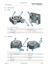
Page 13: ...Housing 2 Roll star output 3 Fixing hole Ø 6H7 2x 4 Mounting hole for M10 4x 5 Input shaft drive 3 3 2 TMF850 2000 Fig 3 Rotary indexer structure TMF850 TMF2000 1 Roll star output flange output 2 Input shaft drive 3 Housing 4 Position indicator 5 Vernier 6 Cable aperture 7 Service apertures 8 Oil sight glass 9 Oil drain plug 3 4 1 2 5 9 8 7 6 5 4 3 1 2 ...

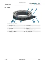
Page 14: ...sion 1 0 3 3 3 TMF3000 5000 Fig 4 Rotary indexer structure TMF3000 TMF5000 1 Roll star output flange output 2 Drive unit 3 Input shaft drive 4 Housing 5 Position indicator 6 Grease nipple 7 Vernier 8 Cable aperture 9 Service apertures 10 Oil sight glass 11 Oil drain plug ...

Page 15: ... 3 3 4 TMF8000 Fig 5 Rotary indexer structure TMF8000 1 Cable aperture 2x 2 Roll star output 3 Oil filler plug 4 Input shaft drive 5 Oil sight glass 6 Oil drain plug 7 Housing 8 Threaded hole M36 3x for eyebolt 9 Mounting hole Ø 26 15x 10 Fixing hole Ø16H7 2x 5 6 8 9 10 7 1 4 3 2 ...

Page 16: ...attachments NOTICE Damage to components Improper transport can cause material damage Carry out transport carefully and note the symbols on the packaging Align the lifting eyes in the direction of the load Follow the operating instructions for the lifting gear Check the delivery immediately on receipt for completeness and transport damage In the event of externally visible transport damage observe ...

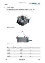
Page 17: ...re they are functioning properly The angle between the vertical and the chain sling or sling strap must be between 0 and 45 Fig 6 Transport with eyebolts Fig 7 Lifting instructions Recommended slings Type Quantity Sling Screw size TMF1000 3 VLBG 0 63t M10 TMF2000 3 VLBG 1t M12 TMF3000 3 VLBG 1t M12 TMF4000 4 VLBG 1t M12 TMF5000 4 VLBG 1t M12 TMF8000 3 VLBG 8t M36 ...

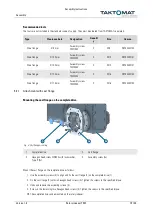
Page 18: ... drive can cause material damage The type of drive e g a servomotor or three phase a c motor must be agreed with TAKTOMAT On attaching the drive note and follow the manufacturer s operating instructions The oil level check and drain plugs and the vent valves must be freely accessible Note the spatial positions of the drive Fix the drive in the specified mounting points Tighten the screws to the sp...

Page 19: ...ange Ø 17 5 mm Assembly screw TMF5000 2 M16 ART00332103 5 2 1 Attachment with cast flange Mounting the cast flange on the complete drive Fig 9 Cast flange mounting 1 Complete drive 2 Cast flange 3 Hexagon head screw DIN933 with lock washer Type S 8x 4 Assembly screw 2x Mount the cast flange on the complete drive as follows 1 Use the assembly screws 4 to align and fix the cast flange 2 on the compl...

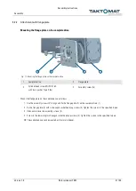
Page 20: ... 8x 3 Stud DIN 939 8x 4 Rotary indexer Attach the complete drive to the rotary indexer as follows The cast flange is mounted on the complete drive 1 Screw in the eight studs 3 up to the limit stop 2 Push the complete drive 1 onto the drive shaft until the cast flange is positioned flush against the rotary indexer 3 Fix the complete drive on the rotary indexer 4 using eight nuts 2 and lock washers ...

Page 21: ...ype S 8x 4 Assembly screw 2x Mount the flange plate on the complete drive as follows 1 Use the assembly screws 4 to align and fix the flange plate 2 on the complete drive 1 2 Fix the flange plate 2 with six hexagon socket head cap screws 3 Tighten the screws to the specified torque 3 Undo and remove the assembly screws 4 4 Screw in the remaining two hexagon socket head cap screws 3 Tighten the scr...

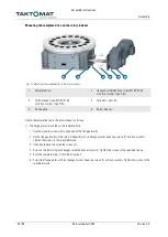
Page 22: ...indexer as follows The flange plate is mounted on the complete drive 1 Use the assembly screws 4 to align and fix the flange plate 5 2 Fix the flange plate 5 on the rotary indexer 6 with six hexagon socket head cap screws 3 and lock washers Tighten the screws to the specified torque 3 Undo and remove the assembly screws 4 4 Screw in the remaining two hexagon socket head cap screws 3 Tighten the sc...

Page 23: ...t 1 Screw M12 DIN 933 with lock washer S12 2 Complete drive 3 Spigot Ø230 4 Housing TMF8000 Assemble the complete drive as follows 1 Push the complete drive 2 onto the drive shaft until it is positioned flush on the spigot 3 2 Fix the complete drive with the screws 1 Tighten the screws to the specified torque 4 2 3 1 ...

Page 24: ...ments 4 Compare the supply voltage with the data on the nameplate 5 Connect the drive unit 6 Earth the housing of the rotary indexer with an adequate cross section Setting the zero point using the vernier The vernier is used to set the zero point The vernier can be used to always set the roll star output flange to the factory zero position of the rotary indexer This is necessary for applications t...

Page 25: ...on to the next The rotational direction of the roll star output flange corresponds to the rotational direction of the drive The rotational direction of a three phase a c motor can be reversed by swapping two phases of the supply voltage Reversing operation reciprocating operation In this mode the roll star output flange oscillates shuttles continuously back and forth between two positions The driv...

Page 26: ...or noises Operator Monthly Check the rotary indexer for oil leakage Operator Monthly Check the oil level Check the safety markings for legibility Operator Half yearly Check for damage visual inspection Remove dust deposits especially on the ventilation grille of the drive unit Check electric cables for damage Qualified personnel Half yearly additionally for TMF8000 Visual inspection of the belt dr...

Page 27: ... a standstill Do not overfill oil Fill the oil only up to the level of the oil sight glass Fig 15 Checking the oil level 1 Oil drain 2 Oil sight glass 3 Oil fill The rotary indexer has an oil sight glass and must be checked for correct oil level in accordance with the maintenance plan The correct oil level is reached when the oil is in the middle of the oil sight glass 2 Top up oil if necessary 7 ...

Page 28: ...le lubricant Mixing greases with different bases leads to gumming and decomposition of the greases and cancels the lubricating effect Use lithium saponified grease only for relubricating Lubricating oils Only use lubricating oils to DIN 51 517 ISO VG 460 Recommended gear oils Manufacturer Designation Mobil Mobilgear 600 XP 460 BP Energol GR XP 460 SHELL Omala 460 LIQUI MOLY meguin CLP 460 gear oil...

Page 29: ...to get inside the mechanics Cover holes to protect against penetrating dirt Clean clearance holes and shafts before assembly If clearance occurs in one or multiple stations when checking the rotary indexer the cam followers must be replaced The rotary indexer must be completely disconnected from the power supply to ensure that the dismantling and maintenance of the cam follower are carried out saf...

Page 30: ...e the retaining ring 3 with retaining ring pliers 3 Dismantle the hexagon head screw 4 together with the two washers 5 and 6 An internal thread inside the roll sleeve becomes exposed 4 Screw an internal extractor into the internal thread of the roll sleeve 7 5 With the preceding help of a lubricant use the internal extractor to pull the roll sleeve 7 carefully out of the roll star 6 Heat the outer...

Page 31: ...her 5 and hexagon head screw 4 5 Tighten the hexagon head screw 4 to the specified torque 6 Allow the roll sleeve 7 to cool to ensure easy assembly of the cam follower 8 in the roll start output flange 1 7 Press the roll sleeve 7 without canting into the relevant hole in the roll star output flange 1 up to the limit stop 8 The roll sleeve 7 is held in position by fitting the retaining ring 3 9 Pre...

Page 32: ...drive turns but the rotary indexer does not turn and the roll star output flange has no clearance Worm gear malfunction Safety clutch overload disengaged Input shaft is broken Remove the external blockage engage the safety clutch Contact TAKTOMAT GmbH The drive turns but the rotary indexer does not turn and the roll star output flange has clearance Cam follower ripped off by large overload Contact...

Page 33: ...g materials Materials used The components are mainly made of the following materials Copper complete drive units electrical cables Steel and grey cast iron housings attachments shafts bearings Plastic toothed belts insulation bearings Preparation for disposal 1 Disconnect the system from all power supplies and secure it against being switched on again 2 Wait 15 minutes until all live components ar...

Page 34: ... comply with the technical requirements specified by the manufacturer Only use original spare parts Check spare parts for faults or defects prior to installation Spare and wear parts are always order specific A corresponding spare and wear parts list is available from TAKTOMAT on request When ordering spare parts always specify the serial number The serial number is located on the nameplate ...

Page 35: ... 1 1 2 1 1 3 1 1 5 1 3 2 1 3 3 1 3 4 1 3 7 1 5 3 1 5 4 1 6 1 1 6 4 1 7 1 1 7 4 Reference of the applied harmonised standards according to Article 7 Section 2 EN ISO 12100 2010 Safety of machinery General principles for design Risk assessment and risk reduction Furthermore it is declared that the relevant technical documentation for this partly completed machinery has been compiled according to Ann...

Reviews: