7
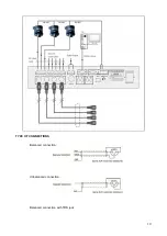
Use this output to display camera video on an external video screen.
19.
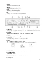
PC CONNECTOR
Connect this socket to your computer to setup the software function.
20-22
. CAMERA CONTROL CONNECTOR RS-422
If you use dome in place of camera you can control pan and tilt move directly from software. Connect
this socket to the control connector of domes..
Note : To know connections, read the user manual of the dome.
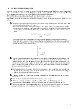
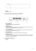
5. CHAIRMAN AND DELEGATE UNIT FUNCTIONS AND CONTROLS
1. Microphone on/off key: Press this key to speak (the unit will be immediately enabled unless
the limit of simultaneously enabled units has been reached), press again to turn off microphone
2. Priority key (for chairman unit only): When press and hold this key 1 second on chairman
3. Indicator light on active microphone: When microphone is active, indicator light switches on
4. Socket to lock the gooseneck microphone (Female)
5. Electret condenser cardioid microphone
6. 8P-DIN (female) socket to connect the system branch cable
microphone unit, all active delegate microphones will be switched off.
7. Microphone socket to fix he gooseneck microphone
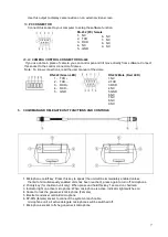
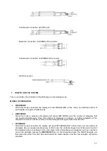
RS-232 (PC) female
1- NC
2- TXD
3- RXD
4- NC
5- GND
6- NC
7- NC
8- NC
9- NC
RS-422 (Green LED)
1- TXD +
2- TXD -
3- RXD +
4- RXD –
5- GND
RS-232 Male (Red LED)
1.NC
2.TXD
3.RXD
4.NC
5.GND
6.NC
7.NC
8.NC
9.NC

