background image

4.1. CONNECTING TO THE MAINS CIRCUIT 

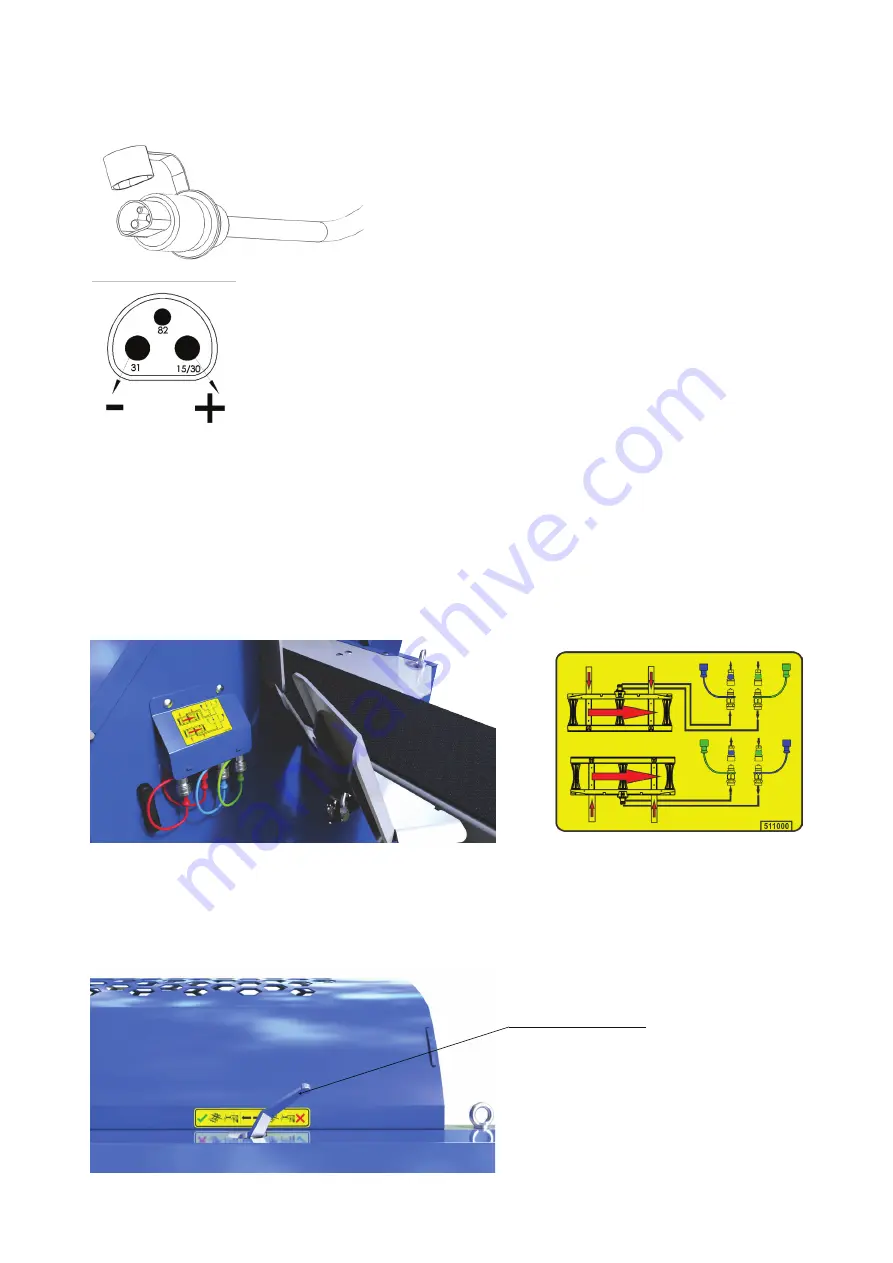
Plug the 3 pin plug into the tractor mains or EP unit 
(optional).

Check that the power source provides a constant 12 V 
voltage and 16 A current; otherwise, this may lead to faulty 
operation of the electrical system. Minimum cross-section 
of the cables from the power source should be 2,5 mm².

4.2. ADDITIONAL EQUIPMENT SETUP

14

4.2.1. ATTACHING THE LOADING DECK TO THE MACHINE’S HYDRAULIC 

CONTROL SYSTEM 

•  Use the quick couplings to connect the loading deck’s hydraulic pipes and the machine couplings. 

To ensure proper connection observe the label and the color covers of the couplings.

•  If the hydraulic couplings are not installed or if the loading deck is not in operation, place the 

selector valve in the appropriate position (X). 

Selector valve

After operation always disconnect the supply cables; otherwise, the tractor battery may begin to 
discharge. 

Summary of Contents for RCA 480 JOY

Page 1: ...FIREWOOD PROCESSOR OPERATING INSTRUCTIONS RCA 480 JOY Ver 2 2 09 2015 ENG Please read these Operating Instructions carefully before installing and using this machine RCA 480 JOY PLUS ...

Page 2: ...MANUFACTURER S ADDRESS Tajfun Planina d o o Planina pri Sevnici 41a 3225 Planina pri Sevnici Slovenia T 386 0 3 746 44 00 F 386 0 3 579 10 16 E mail export tajfun com W www tajfun com 2 ...

Page 3: ...9 3 5 Machine labels and their meaning 10 4 MACHINE SETUP 13 4 1 Connecting to the mains circuit 14 4 2 Additional equipment setup 14 4 2 1 Attaching the loading deck to the machine s hydraulic control system 14 5 MACHINE START UP 15 5 1 In feed conveyor setup 15 5 2 Operating the RCA 480 JOY 16 5 2 1 Turning on the RCA 480 JOY control 16 5 2 2 Description of the RCA 480 JOY control functions 16 6...

Page 4: ...placing the oil filter cartridge 32 7 9 Lubrication of the multiplication gear 32 7 10 Lubrication of the cutting chain 33 7 11 Replacing the cutting chain belt 34 7 11 1 Belt tensioning 35 7 11 2 Cleaning and replacing the air filter 36 7 12 Indications of improper use 37 7 13 Wear and tear parts 37 7 14 Spare parts ordering 37 8 LOADING AND TRANSPORTING 38 8 1 Loading with a forklift 38 8 2 Load...

Page 5: ...chine carefully read these operating instructions Report any faults immediately upon identification The manufacturer s liability for faults becomes void in the following events Improper use The use of unsuitable implements and drives which are not supplied together with the machine The use of other spare parts and tools Rework and modification carried out without manufacturer s prior written agree...

Page 6: ...ord from the mains EP 12 Do not wear loose clothing Keep the operating area clean and tidy Always use caution when operating the machine Moving parts can cause serious injuries in case of improper use of the machine During the running of the machine never leave the machine unsupervised Do not reach into the working area during the operation of the machine Before removing any wedged pieces of wood ...

Page 7: ...achines tractor diesel unit Therefore it is mandatory to wear hearing protectors while operating the machine 2 6 OTHER DANGERS Provided that all safety measures are followed and the machine is being used in accordance with the operating instructions other risks still persist Contact with the machine s moving parts Injuries due to the flying particles of wood Burns due to contact with hot machine p...

Page 8: ...usting the log size cross section See chapter Splitting Transporting logs with the adjustable conveyor adjustable speed height and transversal offset See chapter Conveyor The quality of the logs as well as the machine capacity diminishes when using pre split wood 3 GENERAL 3 3 MACHINE S MAIN COMPONENTS 3 2 DESCRIPTION OF THE MACHINE S FUNCTIONS These operating instructions apply to the following m...

Page 9: ...ic fuse 20 A PTO shaft speed min 400 min RPM max 430 min RPM Maximum splitting pressure 230 bars Oil reservoir volume 100 l 25 gallons Chain lubrication oil reservoir volume 8 l 2 gallons Operating noise level max 92 dB A Weight 1300 kg 2866 lbs Transporter TT 404 TT 404 R Conveyor length 4000 mm 13 Conveyor belt width 430 mm 17 Maximum speed 0 8 m s 31 5 s Weight 180 kg 396 8 lbs Transporter TT 5...

Page 10: ...OP switch 2 Conveyor belt speed 3 Deck control 4 On off switch Machine working area The working area extends in a 3 m radius around the machine Read operating instructions Automatic stopping of the machine after lifting the cover Control handle joystick functions 3 1 2 4 ...

Page 11: ...ety glasses Wear protection gloves Cutting length setting scheme Remaining log length on the in feed conveyor scheme Conveyor movement controls scheme Hydraulic oil reservoir Chainsaw lubrication oil reservoir Direction of the chainsaw drive belt movement ...

Page 12: ...t tension scheme Danger of cutting chain contact Scheme of the deck s hydraulic pipes according to its position The valve handle position when operating with or without the deck Proper direction of the PTO shaft rotation Approved rotational speed range only for RCA 480 JOY For RCA 480 JOY PLUS also see RCA 480 JOY PLUS attachment to RCA 480 JOY operating instructions ...

Page 13: ... SETUP Model Dimensions Compatibility PTO Shaft C Line T 6BR KK560 1 3 8 Z6 1 3 8 Z6 LKK 560 EP 12 RCA 330 JOY RCA 380 RCA 400 JOY RCA 480 JOY PTO Shaft C Line T4 DZ DZ BR KK510 1 3 8 Z6 2X LKK 510 RCA 330 JOY RCA 380 RCA 400 JOY RCA 480 JOY When using our machines we recommend Tajfun PTO Shafts The tractor output shaft and machine input shaft should be positioned as parallel as possible Otherwise...

Page 14: ... EQUIPMENT SETUP 14 4 2 1 ATTACHING THE LOADING DECK TO THE MACHINE S HYDRAULIC CONTROL SYSTEM Use the quick couplings to connect the loading deck s hydraulic pipes and the machine couplings To ensure proper connection observe the label and the color covers of the couplings If the hydraulic couplings are not installed or if the loading deck is not in operation place the selector valve in the appro...

Page 15: ... throttle to minimum Lift the machine cover to disengage the safety switch and disable all the main functions of the machine Engage the PTO shaft drive and start the machine Manually add throttle to set the required PTO shaft rotational speed 420 min Install the machine cover Check the function of the emergency STOP switch EMERGENCY SHUTDOWN Follow the RCA 480 operating instructions See chapter Op...

Page 16: ...or in the left or right direction Backward sawing two phase fixing the log and starting up the cutting chain which is followed by the chainsaw movement Forward splitting push the handle in the forward direction briefly do NOT hold it this position The control handle buttons Yellow buttons moving the splitting wedge up down Red button returning the splitting cylinder home from any position Green bu...

Page 17: ...ditional functions conveyor UP DOWN raising and lowering the conveyor by means of a hydraulic winch LEFT RIGHT moving the conveyor left and right 15 to each side Warning The speed of these functions depends on the conveyor belt speed valve settings If the speed is set too low the hydraulic winch brake remains engaged and the winch does not operate C A B D ...

Page 18: ...45 by moving the control handle up or down Conveyor TT 404 and TT 504 Shut off the valve completely and press and hold the yellow button on the main control handle of the machine until the conveyor is extended to its maximum Conveyor TT 510 S TT 404 R TT 504 R Turn the valve into the expanding position and press and hold the yellow button on the main control handle of the machine until the conveyo...

Page 19: ... factory default setting Activate the feeding by pushing the control handle to the right The feeding can be stopped at any time when the log reaches the cutting length limiter by pushing the handle to home neutral position To activate the feeding in the opposite direction push the control handle to the left Safety pin Conveyor TT 510 S TT 404 R TT 504 R Conveyor TT 404 and TT 504 Remove the suppor...

Page 20: ...n The force used by the cylinder to push the saw bar is factory set and must not be modified The saw bar operation speed is also set to a fixed value The sawing speed varies depending on the sharpness of the cutting chain and type or diameter of wood Prior to sawing always check the sharpness and tension of the chain and the level of the chain lubrication oil The wood must remain in the fixed posi...

Page 21: ...adjusting the position of the cutting length limiter by fixing it in the desired position with a screw Cutting length limiter 6 3 2 REMOVING SAWDUST The channel for removing the sawdust is equipped with a hatch which must be closed if the machine is connected to the suction unit for extracting wood pieces and sawdust XE 10 XE 10 Hy XE 11 Hy etc When operating without a suction unit open the hatch ...

Page 22: ...ll into the splitting chute diagonally If this happens open the cover and reposition the piece of wood prior to splitting Problems may also be caused by wood pieces that were cut sideways particularly the last piece These pieces can lift up during splitting and damage the machine 6 4 1 ADJUSTINGTHEHEIGHTOFTHESPLITTINGWEDGEANDREPLACING THE SPLITTING WEDGE RCA 480 JOY Lift or lower the splitting wed...

Page 23: ...ting up to the max diameter specified on your RCA machine 2 The log in the splitting chute must always be longitudinally directed towards the splitting wedge This prevents unnecessary overloads and downtime 3 The log in the splitting chute must always be centred on the vertical blade of the splitting wedge This prevents overloading of the side blades of the splitting wedge ...

Page 24: ...of the splitting wedge to be slightly less than the mechanism permits This allows the splitting wedge to still breathe during the splitting so as not to burden the mechanism and the lower blades of the wedge Failure to observe the instructions may result in mechanical damage to the wedge and the machine that is not subject to reclamation ...

Page 25: ...d and the splitting cylinder and the saw bar return to the home position Lifting the machine cover has the same function as the main safety switch Manual interventions around the log are possible only after opening the machine cover and stopping the machine Close the machine cover and disengage the safety switch to continue sawing and splitting To restore all machine functions push the green RESET...

Page 26: ...idues they can clog the area behind the splitting cylinder and prevent the cylinder from returning to the home position This can increase the pressure during machine idling as well as cause overheating 2 Wood residues under the conveyor drive cylinder can damage the conveyor belt 3 Sawdust ejected by the chainsaw must be removed regularly to prevent the sawdust to fill up the drain channel 1 2 3 ...

Page 27: ... in the hydraulic system After 5 000 hours of operation or once every two years See chapter Changing the hydraulic system oil Replace the oil filter cartridge After first 200 hours of operation Later after every 1000 hours of operation When changing the oil or if the filter gauge indicator is in the red zone Replace the filter cartridge Change the multiplication gear oil After the first 50 hours o...

Page 28: ...s loud The PTO shaft rotational speed is too high Verify that the PTO shaft rotational speed is between 400 to 430 RPM Low level of the multiplication gear oil Check the oil level and top it if necessary The PTO shaft with an in built clutch is loud We advise against using PTO shafts with clutches since they can damage the drive parts Use the regular PTO shaft or PTO shaft with two wide angle join...

Page 29: ...om the lifting mechanism Reinstall the splitting wedge inside the lifting mechanism The drive belt is torn The speed of the PTO shaft is too low and the chain is worn out and is not tensioned Replace the belt and use proper settings during operation The belt is not tensioned sufficiently Replace the belt The chainsaw was blocked during sawing because the wood was not sufficiently fixed Replace the...

Page 30: ... sure the cutting teeth are turned in the right direction the cutting edge on the top of the saw bar must face the machine controls Replace the cutting chain by carrying out the above steps in the reverse order but do not forget to tension the chain at the end Remove sawdust from the saw bar holder lubrication grove and the saw bar Wait 2 to 3 minutes for the new cutting chain to run in Afterwards...

Page 31: ...upper side of the saw bar somewhere in the middle for approximately three fourths of the gear teeth height Always wear gloves when checking the chain tension to prevent cutting your fingers on the sharp chain 7 5 ANGLES USED FOR SHARPENING THE CUTTING CHAIN Figure shows the angles for sharpening the DuraCUT 3 8 chain which is used for firewood processors 1 Cutting depth 0 025 0 65 mm difference be...

Page 32: ...ckers I 286 S M 2950 S Cincinnati Milacron P 68 P 69 P 70 7 8 REPLACING THE OIL FILTER CARTRIDGE Replace the filter cartridge for the first time after 200 operating hours then every 1 000 operating hours The filter cartridge is not washable Reduced filter permeability can be observed on the filter gauge if the gauge indicator is in the red zone when the oil is heated to the operating temperature i...

Page 33: ...h quality chain lubrication oils with viscosity grade of 95 mm s at 40 C are recommended The flow of the cutting chain lubrication oil can be regulated depending on the oil quality by means of a regulation screw The flow is factory set to maximum Never operate the machine without lubricating the chain first Do not use spent oil ...

Page 34: ...over hydraulic pipe 3 spring screws Unscrew the lubrication pump Loosen the belt tensioner Remove the belt from the driven pulley Remove the old belt and clean the drive assembly Insert a new belt Install the belt on the pulley Tension the belt and re attach the elements lubrication pump drive cover with filter ...

Page 35: ...necessary to allows the notch to align Tighten the safety nut Screw the spring screws and apply LOCTITE 222 or equivalent Ensure that the distance X is 17 mm Attention Do not fully compress the spring since this prevents the operation of the clutch Fasten the hydraulic pipe After one hour of test run recheck the belt tension first disconnect the machine from the drive Afterwards recheck the belt t...

Page 36: ...ce X which should be between 16 and 17 mm The distance for all three screws must be THE SAME LENGTH Attention If the spring is completely compressed the clutch will not work Tighten the hydraulic tube and finally secure the drive protection CLEANING THE FILTER Remove sawdust and waste from the top of the filter the cover to allow free air flow to the inside of the saw drive Regularly clean and cha...

Page 37: ...porates the following wear and tear parts which are replaced by the customer if necessary These parts are not covered by warranty defined under the warranty statement Chain Drive sprocket Chain guide saw bar Chain drive belt Clutch plates Conveyor wire rope In feed conveyor Conveyor belt Splitting wedge Oil Air filter Oil filter 7 14 SPARE PARTS ORDERING When ordering spare parts provide the follo...

Page 38: ...38 8 LOADING AND TRANSPORTING 8 1 LOADING WITH A FORKLIFT The loading with a forklift can be carried out from two sides LONGITUDINALLY ...

Page 39: ...8 2 LOADING WITH THE HELP OF LIFTING STRAPS 39 TRANSVERSELY L 3 m ...

Page 40: ... calculate the weight mass IF min use the following formula IF min kg Minimum mass of the front weights IR kg Total mass of the machine attached at the rear 1480 kg RCA 480 JOY TF kg Front axle load of an empty tractor TE kg Weight of an empty tractor a m Distance between the center of gravity of the front weight and the centre of the front axle b m Tractor wheelbase c m Distance between the cente...

Page 41: ...achinery Safety Rules Official Gazette of the Republic of Slovenia No 75 2008 Directive 2006 42 EC in compliance with the following standards EN ISO 4254 1 2009 EN ISO 12100 2010 EN ISO 13857 2008 EN 349 1993 A1 2008 EN 609 1999 A2 2009 ISO 4413 2010 Authorized person for technical documents operating at the manufacturer s location is also the signee of this statement Planina 20 05 2020 Iztok Špan...

Page 42: ...ignature factory number year of manufacture The warranty certificate shall only be deemed valid together with the original invoice The warranty covers defect of the material and workmanship If repairs are carried out by unqualified personnel or if other than original spare parts were used the warranty shall become void Our warranty also becomes void as follows If these operating instructions are n...

Page 43: ...43 ...

Page 44: ...44 ...

Reviews: