background image

29

Installation

Anti-siphon check valve

This pump is provided with an anti-siphon check valve. Use this valve at the injection point unless there is a good rea-
son not to do so. Be absolutely sure to install it in the following cases.
•  When the injection point is open to the atmosphere and liquid is to be injected at a position lower than the level of the 

liquid in the tank (prevention of siphoning)

• When the liquid is to be injected inside the suction-side pipe of a volute pump, etc.
• When a chemical greatly exceeding the pump’s rated discharge volume is being fed (prevention of overfeed)

 Even with a rising pipe, overfeed may occur if the pipe is too long.

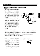
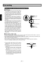
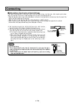
(1) The anti-siphon check valve has an R1/2 external thread. Provide an Rc1/2 internal thread at the injection point.

Connecting

Main pipe

Injection point
(Rc1/2)

Nylon tube

Cap nut

Sleeve

Valve body

Assembled state

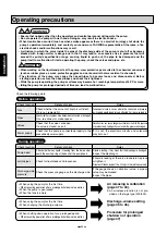
IMPORTANT

•  Be sure to securely connect the nylon tube and anti-siphon check valve as well as the anti-siphon 

check valve and injection point.

•  The anti-siphon check valve will be corroded by some chemicals, and so such chemicals cannot be 

used.  For special chemicals, consult with a TACMINA representative separately.

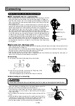
(2) Remove the cap nut and sleeve, and attach only the valve body to the main pipe (injection point).
(3)  Pass the nylon tube through the cap nut and sleeve, and firmly insert its end until it touches the back end of the 

groove in the valve body.

(4) In this state, tighten the cap nut by hand as far as it can be turned.
(5) After tightening the cap nut by hand, use a wrench to tighten the cap nut two or three more turns.

09-32̲PZD総合取説̲E.indd   29

09-32̲PZD総合取説̲E.indd   29

2010/07/22   8:42:35

2010/07/22   8:42:35

Summary of Contents for PZD Series

Page 1: ...described in this OPERATION MANUAL handle the product according to details of separate meetings drawings and approved documents Please read this OPERATION MANUAL carefully before use Operating the pum...

Page 2: ...mbient temperature 0 to 40 C Ambient humidity 35 to 85 RH Temperature of liquid 0 to 40 C no freezing Viscosity of liquid Less than 50 mPa s Altitude of installation location Less than 1 000 m Environ...

Page 3: ...he supply voltage Do not connect the wires to a power supply that is not within the rated voltage range Operation Maintenance WARNING Ensure that nobody other than the operators and control personnel...

Page 4: ......

Page 5: ...intenance precautions 48 Replacing the diaphragm 49 Replacing the air release nozzle 50 Replacing the valve seats and check balls 51 Replacing the relief valve 57 Operating precautions 35 Control pane...

Page 6: ......

Page 7: ...braided hose 6 11 PE tube 6 8 or 1 4 3 8 Relief air release hose 1m installed Soft PVC hose 4 6 INSULOK spare for relief air release hose 1 piece Anti siphon check valve 1 set R1 2 Foot valve 1 set C...

Page 8: ...1 4 3 8 Air release hose 1m Soft PVC hose 4 6 Anti siphon check valve 1 set R1 2 Foot valve 1 set Ceramic weight 1 set Pump mounting nuts bolts 2 sets M5 30 Operation manual 1 copy Liquid end Material...

Page 9: ...s M5 30 Operation manual 1 copy Liquid end Material ATCF Model 30R 60R 100R Hose tube 3m PVC braided hose 4 9 PE tube 6 8 or 1 4 3 8 PVC braided hose 6 11 PE tube 6 8 or 1 4 3 8 Relief air release hos...

Page 10: ...djustment dial Pump head Cable ground Description of product This is a solenoid driven diaphragm metering pump with liquid end parts which are resistant to chemicals and with a compact body It can be...

Page 11: ...of the metal parts to rise ultraviolet rays may cause the plastic parts to deteriorate and sand dust and rainwater may damage or corrode the pump body When installing the pump outdoors it is recommend...

Page 12: ...t install the pipes where the chemical may splash onto people even if the hose tube should break When using a pump with a relief valve function always attach a hose for relief purposes and lead the en...

Page 13: ...r cause pipe vibration The pump comes with a 3 meter long hose tube for both the discharge side and suction side If the pressure loss exceeds the pump s maximum discharge pressure thicker pipes will b...

Page 14: ...already been attached to the relief air release port to the tank or other container It is also recommended that a valve meter etc be installed to make it easy to carry out maintenance and other such...

Page 15: ...e tube 5 Attach one end of the air release hose to the air release port and return the other end to the tank or other container It is also recommended that a valve meter etc be installed to make it ea...

Page 16: ...int side end of the tube 3 Return the end of the relief air release hose which has already been attached to the relief air release port to the tank or other container It is also recommended that a val...

Page 17: ...ck valve at the injection point side end of the tube 5 Attach one end of the air release hose to the air release port and return the other end to the tank or other container It is also recommended tha...

Page 18: ...alve of the tank and the suction side joint of the pump using the hose tube When doing this tilt the pipe at a downward gradient so that no air will be trapped inside the pipe 2 Connect the discharge...

Page 19: ...wnward gradient so that no air will be trapped inside the pipe 2 Connect the hose tube to the discharge side joint of the pump 3 Attach a 3 way joint to the discharge side hose tube near the pump s di...

Page 20: ...and the suction side joint of the pump using the hose tube When doing this tilt the pipe at a downward gradient so that no air will be trapped inside the pipe 2 Connect the hose tube to the discharge...

Page 21: ...n force of the hose tube The pump comes with a 3 meter long hose tube for both the discharge side and suction side When longer hose tube is used the pressure loss may exceed the pump s maximum dischar...

Page 22: ...nnecting Small type 30R 60R 100R 30 60 100 31 61 12 Large type 300 500 2 Wind sealing tape around the external thread of the anti siphon check valve and screw the valve into the injection point If it...

Page 23: ...may exceed the pump s maximum discharge pressure so thicker tube will be required Provide details on the 1 viscosity of the liquid 2 length of the pipes how they are positioned and 3 specific gravity...

Page 24: ...al thread of the anti siphon check valve and screw the valve into the injection point If it is hard to screw the valve in grasp the nozzle grip using a tool such as pliers and tighten the valve gently...

Page 25: ...n has started tighten up the cap nuts as appropriate When tightening the cap nuts hold the tube to prevent it from being twisted The joints and other areas may be loos ened by the return force of the...

Page 26: ...k valve has an R1 2 external thread Provide an Rc1 2 internal thread at the injection point Connecting 2 Wind sealing tape around the external thread of the anti siphon check valve and screw the valve...

Page 27: ...e When disconnecting the tube for jobs such as main tenance and then afterwards re connecting the same tube cut about 10 mm off the end of the tube before re using them Connecting Model for injection...

Page 28: ...disconnecting the tube for jobs such as main tenance and then afterwards re connecting the same tube cut about 10 mm off the end of the tube before re using them Connecting Model for injection of gene...

Page 29: ...the tube provide sufficient leeway in the bending so that the tube will not break Also ensure that it will not be rubbed against or trodden on The pump comes with a 2 meter long tube for the discharge...

Page 30: ...1 2 external thread Provide an Rc1 2 internal thread at the injection point Connecting Main pipe Injection point Rc1 2 Nylon tube Cap nut Sleeve Valve body Assembled state IMPORTANT Be sure to securel...

Page 31: ...TCF Anti siphon check valve w duck bill cap This pump is provided with an anti siphon check valve with duck bill cap Use this valve at the injection point unless there is a good reason not to do so Be...

Page 32: ...ce of the hose tube The pump comes with a 3 meter long hose tube for both the discharge side and suction side When longer hose tube is used the pressure loss may exceed the pump s maximum discharge pr...

Page 33: ...ti siphon check valve with duck bill cap has an R1 2 external thread Provide an Rc1 2 internal thread at the injection point 2 Wind sealing tape around the external thread of the anti siphon check val...

Page 34: ...cian or somebody with electrical knowledge Connect the wires after checking the supply voltage Do not connect the wires to a power supply that is not within the rated voltage range Example of wiring W...

Page 35: ...onductors 4 Insert the conductors into the connector holes and use a regu lar screwdriver to secure them firmly 5 After securing the conductors pull them gently to check that they do not come free 6 I...

Page 36: ...rotective goggles and work overalls that are resistant to chemical The vibration of the pump may cause the hoses tubes to become loose and disconnected Before starting operation secure the hoses tubes...

Page 37: ...he stroke speed strokes min ratio or discharge volume mL min is set directly on the control panel Stroke length adjustment dial This is provided only on the large type 300 500 The stroke length of the...

Page 38: ...cluding 6TCT type Air releasing WARNING During the air releasing chemical may suddenly gush out from the pipes and other parts Lead the end of the relief air release hose bank to the tank or other con...

Page 39: ...rt operating the pump 6 Rotate the air release knob clockwise by about 90 degrees The presence of a gap between the knob and retaining nut is now visible 7 After a few moments air will exit from the r...

Page 40: ...e pipe 4 Turn on the pump s power 5 Set the discharge volume to the maximum level See page 41 6 Press the STOP START key to start operating the pump 7 While operating the pump turn the air release kno...

Page 41: ...side pipe 2 Set the stroke length adjustment dial to the 100 marking on the scale 3 Turn on the pump s power 4 Set the discharge volume to the maximum level See page 41 5 Press the STOP START key to...

Page 42: ...s set to 100 prior to shipment 2 Press the key to set the ratio to 100 In the discharge volume setting mode The PZD 30R is used as an example to discribe the instruction 1 Press the MODE SET RESET key...

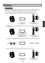
Page 43: ...on Calibration Calibration is a procedure that enables the discharge volume to be set accurately by measuring the maximum dis charge volume under actual operating conditions at the user s and storing...

Page 44: ...ge volume setting screen Change the initial value 30 0 mL min to the actual value 33 0 mL min using the and keys When the MODE SET RESET key is pressed the discharge volume setting screen is restored...

Page 45: ...e volume using the and keys The pump operates for 300 strokes and then stops Maximum discharge volume setting after calibration The stroke speed can be changed even while the pump is operating The rat...

Page 46: ...f the stroke speed Press the STOP START key The pump is set to the operating status and STP is extinguished Stopped Operating STP PS MAN spm mL min STP PS MAN spm mL min STP PS MAN spm mL min STP PS M...

Page 47: ...mL min mL min STP PS MAN spm mL min mL min STP PS MAN spm mL min STOP START MODE SET RST STOP START Display Procedure Description Change the discharge volume mL min using the and keys The discharge v...

Page 48: ...ration Follow the steps below when shutting down the pump for a prolonged period To shut down the pump 1 Check the inside of the tank for any sediment that may have accumulated and check for signs of...

Page 49: ...ant to chemical Before attempting to maintain or repair the pump release the pressure in the discharge pipe discharge the liquid in the pump head and clean the liquid end parts Check the following poi...

Page 50: ...re tightened up in the sequence of 1 3 2 4 the bolts will be tightened unevenly possibly causing the chemical to leak from the pump head 1 3 4 2 Removing the diaphragm 1 Remove the head bolts 2 Remove...

Page 51: ...ith the pump head possibly causing malfunctions and or damage 5 Install the pump head and secure it using the head bolts Replacing the air release nozzle Replacing the air release nozzle 1 If a relief...

Page 52: ...ve Air release knob Air release nozzle assembly Head bolt cross recessed machine screws O ring size P14 O ring size P14 Discharge side joint assembly Valve seat assembly Suction side joint assembly Va...

Page 53: ...assembly Pump head Cap nut Discharge side upper joint O ring size P18 Valve stopper Check ball Discharge side lower joint O ring size P18 Valve stopper O ring size P18 Check ball Suction side joint Ca...

Page 54: ...e lower joint O ring size P18 Valve stopper O ring size P18 Check ball Suction side joint Pump head Cap nut Cap nut Head bolt cross recessed head hexagon bolts Flat washer Discharge side joint assembl...

Page 55: ...Suction side joint Retaining ring Hose nut Ball stopper Check ball Valve seat Pump head Relief valve Air release knob Head bolt cross recessed machine screws Discharge side joint assembly Valve seat...

Page 56: ...bolt cross recessed machine screws Pump head Discharge side joint assembly Valve seat assembly Suction side joint assembly Valve seat assembly Air release nozzle assembly Replacing the valve seats and...

Page 57: ...ssembly discharge side O ring size P12 31 size P14 61 12 Check ball size 4 76 mm diameter 31 size 6 35 mm diameter 61 12 Check ball size 4 76 mm diameter 31 size 6 35 mm diameter 61 12 Air release joi...

Page 58: ...rouble and take steps to prevent its recurrence The relief valve is a consumable Replace it once it has been activated 1 Hold the retaining nut the part shown by the arrow and turn it counterclockwise...

Page 59: ...not become disconnected A situation in which the valve inside the pipe at the discharge side of the pump is shut off or becomes blocked with foreign matter is dangerous in that it may lead to an exces...

Page 60: ...fails to run The pilot lamp does not blink 1 Something is wrong with the power supply or supply voltage 2 The wiring connections for the pump were not performed correctly 3 The power cable is broken...

Page 61: ...6TCT Small type 30 60 100 STCT Large type 300 500 3 Hose standard Size Material 4 9 PVC 6 11 PVC 12 18 PVC 6 8 PE FEP PTFE 9 12 PE 1 4 3 8 PE FEP 3 8 1 2 PE 12 15 PTFE 4 Joint specification Code Type...

Page 62: ...pe S Standard CE CE marking compatible 5 Power plug Code Type EUP Euro plug ULP UL plug AUP Australia plug UKP UK plug JPL Japan lead wire NON No Cable 1 Model discharge volume standard Model Discharg...

Page 63: ...FTCE FTCF FTCT 6TCT STCT VTCET ATCF CL Pump head PVC PVDF SUS316 SUS304 PVC Acrylic PMMA Diaphragm PTFE Check ball Ceramic O ring EPDM Fluoro rubber EPDM Fluoro rubber Special flu oro rubber Pafulo PT...

Page 64: ...wed Ambient humidity 35 to 85 RH Environmental protection IEC standard IP65 or equivalent water and dust proof Altitude of instrallation location Less than 1 000 m Noise level Less than 85 dB Operatio...

Page 65: ...e Air release 4 6 soft PVC hose Max allowable viscosity 50 mPa s Allowable temperature Ambient temperature 0 to 40 C Transferring liquid 0 to 40 C no freezing allowed Ambient humidity 35 to 85 RH Envi...

Page 66: ...ature 0 to 40 C Transferring liquid 0 to 40 C no freezing allowed Ambient humidity 35 to 85 RH Environmental protection IEC standard IP65 or equivalent water and dust proof Altitude of instrallation l...

Page 67: ...0 C no freezing allowed Ambient humidity 35 to 85 RH Environmental protection IEC standard IP65 or equivalent water and dust proof Altitude of instrallation location Less than 1 000 m Noise level Less...

Page 68: ...ater and dust proof Altitude of instrallation location Less than 1 000 m Noise level Less than 85 dB Operation mode Manual Digital settings 3 patterns stroke speed 1 to 300 strokes min in 1 stroke min...

Page 69: ...freezing allowed Ambient humidity 35 to 85 RH Environmental protection IEC standard IP65 or equivalent water and dust proof Altitude of instrallation location Less than 1 000 m Noise level Less than 8...

Page 70: ...min 120 100 80 60 40 20 0 50 100 150 200 250 300 Stroke speed strokes min spm 0 7MPa 0 2MPa Discharge volume mL min Conditions clean water room temperature PZD 30 VTCE VTCF FTCE FTCF FTCT PZD 60 VTCE...

Page 71: ...0 VTCE VTCF spm 0 3MPa 0 1MPa Discharge volume mL min Conditions clean water room temperature Stroke speed strokes min 400 350 300 250 200 150 100 50 0 50 100 150 200 250 300 300 spm 0 2MPa 0 1MPa Dis...

Page 72: ...PZD 100 ATCF 10 0 5 50 100 150 200 250 45 40 35 30 25 15 20 300 1 0MPa 0 2MPa Discharge volume mL min Conditions clean water room temperature spm Stroke speed strokes min 20 10 70 60 40 30 50 80 50 0...

Page 73: ...216 140 PVC UP N E P O PVC UP PZD 30R 60R 100R 30 60 100 FTCE FTCF FTCT Model w relief valve function Model w o relief valve function 118 154 5 7 237 5 140 17 5 78 31 68 150 97 5 195 97 5 237 5 140 7...

Page 74: ...31 68 150 7 155 118 102 176 88 88 PZD 300 500 FTCT 174 5 22 83 255 5 31 68 150 7 155 118 102 183 100 5 82 5 PZD 300 500 STCT 118 102 155 7 150 68 31 255 5 83 174 5 100 5 82 5 183 22 External dimensio...

Page 75: ...el for injection of boiler chemicals PZD CLPZD 30R 60R 100R 30 60 100 ATCF Model w relief valve function Model w o relief valve function 76 76 140 216 7 68 31 150 152 78 16 5 153 5 118 150 68 7 31 216...

Page 76: ...ons prevailing on site use them as a general guide and replace the consumables at an earlier rather than later date Consumables CAUTION The durability of a hose tube relief valve anti siphonal check v...

Page 77: ...phragm protective diaphragm Every 10 000 hours Quantity per pump Check ball Valve stopper 1 Recommended replacement timeframe O ring Every 10 000 hours Every 10 000 hours Part Recommended replacement...

Page 78: ...ion operation of the pump It can be directly attached on the discharge side of the pump Flow indicator The discharge operation can be monitored at a glance by attaching this indicator at the discharge...

Page 79: ...uted at the wishes of individuals such as the user other than TACMINA employees Malfunctions or damages of the warranted product resulting from fires natural disasters geological calamities and forces...

Page 80: ...EM 112 3 1 2010 7 DDD...

Reviews: