


8
SECTION #5 OPERATION OF THE TOUCH PANEL CONTROLLER CONTINUED:
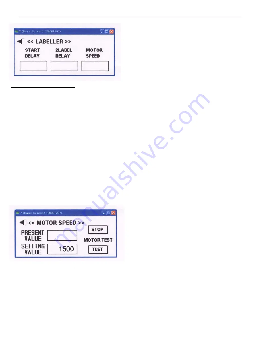
Figure #9
Using the Labeler Sub Menu:
1) From the Home Screen touch where is says Labeller and Figure #9 will appear.
2) To change the value of either the Start Delay or 2 Label Delay, touch the box which will be showing the present
set value. A Numeric Keyboard will be displayed. Input the new desired value and hit the Enter Key in the low-
er right hand corner of the display to save the new value and to return to the Labeler Sub Menu Screen.
3) To change the value of the Motor Speed touch the box below Motor Speed which will be displaying the present
set value. Another screen will come up as shown in Figure #10 below. This screen will show you the present
value. To Change this, touch the box next to Setting Value and a Numeric Keyboard will be displayed. Input
the new desired value and hit the Enter Key in the lower right hand corner of the display to save the new value
and to return to the Motor Speed Screen. The Present Value and the Setting Value will now be the same. At this
time you can press test to view the new speed. To return to the Labeller Sub Menu hit the arrow to the left of
Motor Speed in the upper left hand corner.
Please note that the Start Delay and the Motor Speed will determine the placement of the label onto the
product. This will require some trial and error to get it perfect. Once set, the label placement will be con-
sistent. Suggestion: Do not immediately try to increase the Motor Speed believing it will increase production.
This is incorrect and will only cause variations in label placement.
Figure #10
Using the Option Sub Menu:
1) From the Home Screen touch the Options Box and it will bring you to the Option Sub Menu.
2) To use the Option Sub Menu, simply touch the box next to the desired Option that is to be turned on or off.
Example, to turn on the Target Counter, touch the On box to the right of the word Target. If you desire 2 Label
operation, touch the 2 Label Button at the bottom right of the screen. To change to 1 Label, simply touch the 1
Label box.
3) See Figure #11 for a view of the Option Sub Menu.
Summary of Contents for Mini-Con R
Page 11: ...11 SECTION 8 TROUBLE SHOOTING...
Page 12: ...12 SECTION 9 PARTS LIST...