background image

10 

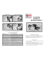
SECTION #6 OPERATION OF THE TACH-IT MINI-CON LABELER CONTINUED: 


7)  If any adjustments need to made to the labeller, make the necessary adjustments. 


8)  The labeller is now ready for use. 


SECTION #7 ADJUSTMENT TO THE SENSITIVITY OF THE STOP SENSOR (A-3): 


The Stop Sensor (A-3) used on this machine is designed to read the gap (die cut) between the labels.  If the labels 
continue to run, it may be necessary to change the sensitivity of the Stop Sensor.  Instructions for this are as follows: 
 
The LED signal strength indicator (yellow) lights continuously when there is optimum light reception. If it does not 
light, too little light is received: Increase the sensitivity using the “+” key. 
 
Checking object detection: 
Place object in light beam; the LED signal strength indicator 
(yellow) must switch off. If it remains lit, reduce the 
sensitivity on the “–” key until it switches off. The LED 
signal strength indicator (yellow) must light again after the 
object has been removed. If this is not the case, correct the 
sensitivity using the “+” key until the switching threshold is set correctly. 

Summary of Contents for Mini-Con R

Page 1: ...South Hackensack New Jersey 07606 USA Tel 201 440 5500 Toll Free 800 222 5540 Fax 201 440 1455 Email sales tach it com Website www tach it com Clements Industries Japan Clements Industries Inc Korea...

Page 2: ...ne Page 4 Section 4 Loading of the Labels Page 5 Section 5 Operation of the Touch Panel Controller Page 7 Section 6 Operation of the Tach It Mini Con Labeler Page 9 Section 7 Adjustment to the Sensiti...

Page 3: ...osive materials or fumes are present Any modification to the machine makes the warranty null and void Service on this machine should only be performed by factory trained authorized service personnel N...

Page 4: ...nveyor and when the item enters the Vertical Conveyor the product rotates smoothly and consistently and without hesitation 4 Load the labels per Section 4 of this manual 5 Locate thee Label Head Heigh...

Page 5: ...e Figure 3 1 Locate the Label Hanger Inside A 1 1 and the Label Hanger Outside A 1 2 The dif ference between the 2 is that the Label Hander Inside A 1 1 uses a Set Screw to lock it into place while th...

Page 6: ...per and around the Dispensing Plate A 6 At this point pull off about 18 inches of the labels from the roll and feed it around the Dispensing Plate so that 0 5mm to 1mm of a label is beyond the edge of...

Page 7: ...that the Touch Panel Controller has been set to work with the Hot Stamp Printer Target If highlighted this shows that the Target Counter Feature is enabled Labeller This leads to a sub menu that allow...

Page 8: ...o the Motor Speed Screen The Present Value and the Setting Value will now be the same At this time you can press test to view the new speed To return to the Labeller Sub Menu hit the arrow to the left...

Page 9: ...hes for each conveyor and turn them on 5 Complete the set up described in Section 5 of this manual to utilize the options desired and to make sure that label placement is where needed If this is not c...

Page 10: ...Stop Sensor Instructions for this are as follows The LED signal strength indicator yellow lights continuously when there is optimum light reception If it does not light too little light is received I...

Page 11: ...11 SECTION 8 TROUBLE SHOOTING...

Page 12: ...12 SECTION 9 PARTS LIST...

Reviews: