background image

SECTION #4 LOADING OF LABELS CONTINUED: 

 
3)  Verifying that the labels are feeding off the bottom of the roll, take the leading edge of the labels and bring it 

over A-10 Tension Roller and then in between Roller #3 and the Urethane Wiper.  There is a thumb screw that 
will allow the Urethane Wiper to swivel.  Once the labels are past this point, adjust the Urethane wiper to add 
tension to the label web if needed.  Many times added tension is not needed. 
 

4)  Continue feeding the leading edge of the labels to the Stop Sensor (A-3) and in between the 2 halves of the  

sensor.  This sensor will read the gap in between the labels and determine when the feed portion of the cycle will 
stop.  There is an arrow at the end of the sensor that shows will the actual reading of the gap will occur. 
 

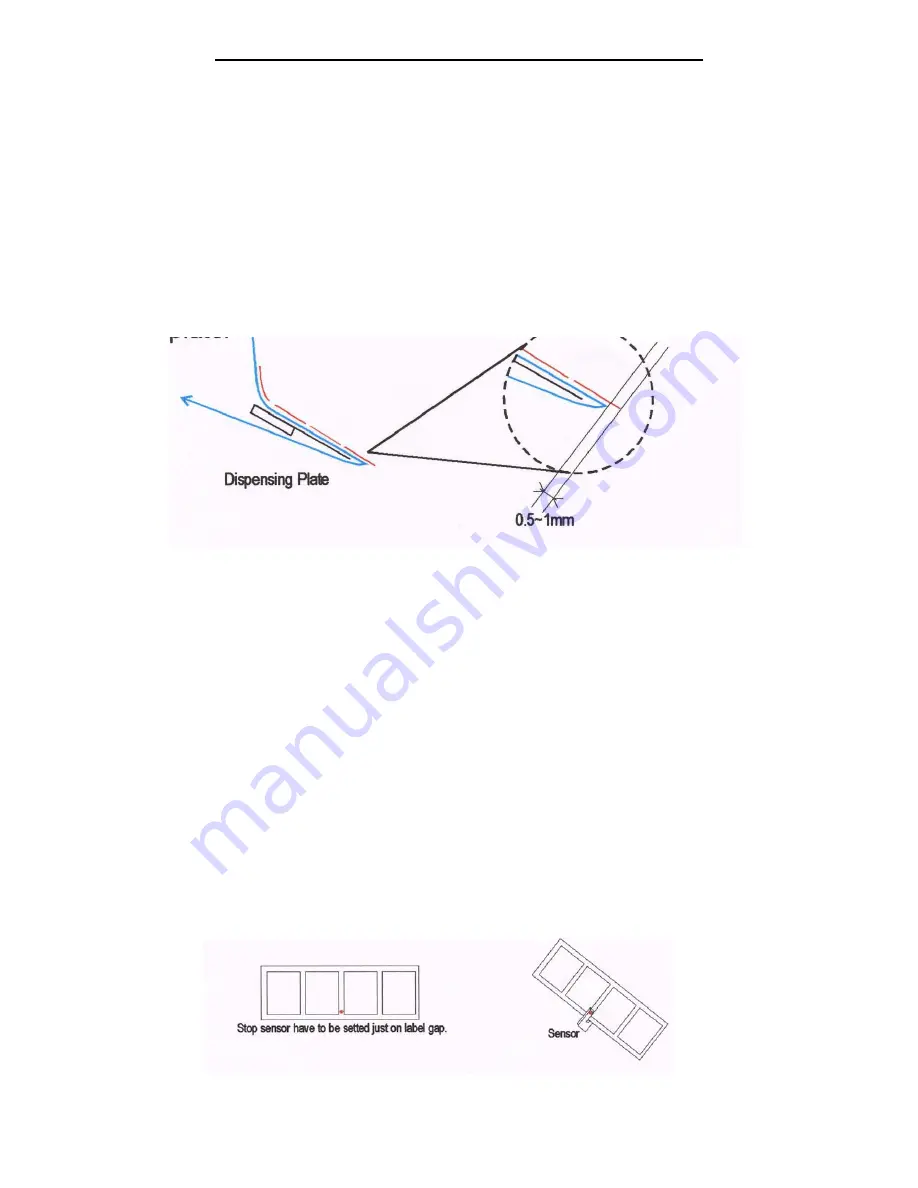
5)  Feed the leading edge of the labels behind roller #4 on Figure #4 and then under the Urethane Wiper and around 

the Dispensing Plate A-6.  At this point pull off about 18 inches of the labels from the roll and feed it around the 
Dispensing Plate so that 0.5mm to 1mm of a label is beyond the edge of the Dispensing Plate per Figure 5. 


6)  Making sure that the Black Handle located between the Press Rollers #5 and #6 on Figure #4, is in the open  

position, bring the leading edge of the labels up and over the purple neoprene roller #5 into the space between 
rollers #5 and #6 and then under roller #6.  
 

7)  Continue feeding the labels around #7 as per Figure #4 and then using the U-Clip secure the labels to the  

Re-winder (A-9).   
 

8)  At this point, locate the Stop Sensor (A-3) and note that the Stop Sensor is mounted to a rail which allows for the 

position of the Stop Sensor to be adjusted.  Loosening the screw, adjust the position of the Stop Sensor so that 
the gap in the label is located in the middle of the Stop Sensor per Figure #6. 
 

9)  At this point, put the Black Handle located between Rollers #5 and #6 to the closed position. 


10) The machine is now fed and ready for use. 

Figure #5 

Figure #6


Summary of Contents for Mini-Con R

Page 1: ...South Hackensack New Jersey 07606 USA Tel 201 440 5500 Toll Free 800 222 5540 Fax 201 440 1455 Email sales tach it com Website www tach it com Clements Industries Japan Clements Industries Inc Korea...

Page 2: ...ne Page 4 Section 4 Loading of the Labels Page 5 Section 5 Operation of the Touch Panel Controller Page 7 Section 6 Operation of the Tach It Mini Con Labeler Page 9 Section 7 Adjustment to the Sensiti...

Page 3: ...osive materials or fumes are present Any modification to the machine makes the warranty null and void Service on this machine should only be performed by factory trained authorized service personnel N...

Page 4: ...nveyor and when the item enters the Vertical Conveyor the product rotates smoothly and consistently and without hesitation 4 Load the labels per Section 4 of this manual 5 Locate thee Label Head Heigh...

Page 5: ...e Figure 3 1 Locate the Label Hanger Inside A 1 1 and the Label Hanger Outside A 1 2 The dif ference between the 2 is that the Label Hander Inside A 1 1 uses a Set Screw to lock it into place while th...

Page 6: ...per and around the Dispensing Plate A 6 At this point pull off about 18 inches of the labels from the roll and feed it around the Dispensing Plate so that 0 5mm to 1mm of a label is beyond the edge of...

Page 7: ...that the Touch Panel Controller has been set to work with the Hot Stamp Printer Target If highlighted this shows that the Target Counter Feature is enabled Labeller This leads to a sub menu that allow...

Page 8: ...o the Motor Speed Screen The Present Value and the Setting Value will now be the same At this time you can press test to view the new speed To return to the Labeller Sub Menu hit the arrow to the left...

Page 9: ...hes for each conveyor and turn them on 5 Complete the set up described in Section 5 of this manual to utilize the options desired and to make sure that label placement is where needed If this is not c...

Page 10: ...Stop Sensor Instructions for this are as follows The LED signal strength indicator yellow lights continuously when there is optimum light reception If it does not light too little light is received I...

Page 11: ...11 SECTION 8 TROUBLE SHOOTING...

Page 12: ...12 SECTION 9 PARTS LIST...

Reviews: