background image


10


   Functional specification: 

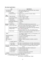
Item Specification 

Input Signal Type 

PNP type (SOURCE) input (External 24VDC Input is allowed) 

Control Method 

Sinusoidal wave PWM control 

Freq. Range 

1~200 Hz*1 

Resolution Setting 

Digital:  0.1 Hz  (1 ~ 99.9 Hz); 1 Hz (100 ~ 200 Hz) 

Analog: 1Hz/ 60 Hz 

Keyboard Setting  

Directly setup by 

▲▼

 buttons. 

External Signal Setting 

0~10V, 4 ~ 20mA, 0 ~ 20mA 


Freq. 

Control 


Other function 

Frequency upper and lower limit 

Carrier frequency 

4~16KHz*2 

Accelerate/Decelerate time 

0.1~ 999 Sec 

V/F Pattern 

6 Patterns 

Torque control 

Torque boost level adjustable (manual torque boost) 

Multi-Functional input 

2 point, to be used as multi-speed 1(Sp.1) / multi-speed 2(Sp.2) *1/ 
Jog / External emergency stop / External bb / Reset 

Multi-Functional output 

1a Relay terminal, to be setup as Fault / Running / Frequency.  

Braking Torque 

 1P2~

101

/2P2~201:About 20% 

 202/203/401/402/403: 20%~100%, built-in braking transistor 


General 

Control 


Other function 

Decelerate or free run stop, Auto reset, DC braking frequency / 

Voltage / Time can be setup by constants. 

Display 

Three digital LED display frequency / inverter parameter / fault 

record / program version. 

Operating temperature 

-10 ~ +40

O

C (without shield sticker: -10

O

C ~ +50

O

C) 

Humidity 

0~95% RH non-condensing. 

Vibration 

Under 1 G  (9.8 m/s

2

EMC specification 

EN5008-1, EN5008-2, EN50082-1, EN50082-2, EN50178 

UL  

UL508C 

Overload protection 

150% for 1 min. 

Over-voltage  

DC voltage > 410V(100/200 series); DC voltage > 800V(400 series)

Under voltage 

DC voltage < 200V(100/200 series); DC voltage < 400V(400 series)

   Momentary Power-loss  

0 ~ 2 sec: The inverter can be restarted using speed search  

                 feature.  

Stall Prevention 

During Acceleration / Deceleration/ Constant speed 

Output Short-circuit 

Electronic circuitry protection 

Grounding fault 

Electronic circuitry protection 


Protection 

Function


Other function 

Heat sink overheat protection, Current limit 

Installation 

Mounting screw or DIN rail (Option). 


Note: *1:


New function for CPU version v1.9 and above.


*2:  Carrier frequency range: CPU version v1.6 is 4~8kHz. 

                                                              CPU version v1.9 and above are 4~16kHz. 
 

Summary of Contents for E2 Series

Page 1: ...icroprocessor Controlled IGBT Drive Inverter Motor Speed Regulator Operating Manual High Performance Adjustable Speed Micro Drives E2 Series 110V 0 2 0 75KW 0 53 1 6KVA 220V 0 2 2 2KW 0 53 4 0KVA 440V...

Page 2: ...ment 7 2 Sample Model No Identification 8 3 Specifications 9 4 Wiring 15 5 Dimensions Location of terminal block 18 Chapter 3 Software Index 1 Keypad Operating Instructions 27 2 Parameters List 28 3 P...

Page 3: ...turning off the power before the charging indicator went off z Do not attempt to wire circuitry while power is on Do not attempt to examine the components and signals on the PCB while the inverter op...

Page 4: ...verter z Check to see if the model number of the AC inverter matches the model number of the AC inverter that you ordered z Check to see whether any damage occurred to the AC inverter during shipment...

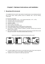
Page 5: ...injury or damage to the inverter itself z Install the inverter onto a firm metal base plate or another non flammable type material Do not install the inverter onto or nearby any flammable material z A...

Page 6: ...t the inverter still has enough storage power to control the circuit therefore when power is regenerated the inverter will automatically start operation again depends on the setup of F_23 When restart...

Page 7: ...Please reconfirm the operating range of motor and the machinery you are controlling z Do not examining the signals on the PCB of the inverter when it is under operation z All inverters are properly ad...

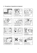
Page 8: ...vironments Keep away from rain or where dripping water may get into the inverter Avoid metal dust and dusty environments Avoid massive vibration Avoid excessive direct heat Avoid where environmental t...

Page 9: ...foreign dusts flocks or metal scraps from entering interior z Avoid electric magnetic interference soldering or power machinery z Avoid vibration if vibration cannot be avoided an anti rattle mounting...

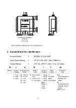
Page 10: ...Power Voltage Horse Power Rated Model Type Power Supply Filter Option Enclosure Type Ventilation Installation Direction Front View 1 110V 2 220V 4 440V P2 0 25 Hp P5 0 5 Hp 01 1 Hp 02 2 Hp 03 3 Hp M C...

Page 11: ...Output Current A 1 4 2 3 4 2 7 5 10 5 Capacity KVA 0 53 0 88 1 6 2 9 4 0 Rated Weight Kg 0 76 0 77 0 8 1 66 1 76 Input Voltage Max Single Three phases 200 240V 10 15 50 60Hz 5 Output Voltage Max Three...

Page 12: ...ction Decelerate or free run stop Auto reset DC braking frequency Voltage Time can be setup by constants Display Three digital LED display frequency inverter parameter fault record program version Ope...

Page 13: ...mm2 Terminal screw M3 Wire dimension 14AWG 2 0m m2 Terminal screw M3 M4 Wire dimension 3 5mm2 Terminal screw M4 Wire dimension 3 5mm2 Terminal screw M4 Signal Terminal TM2 1 11 Wire dimension 0 75mm2...

Page 14: ...The Magnetic Contact can be omitted at ordinary operation To utilize external control automatic restart or breaking controller the magnetic contact must be added at the primary side z Do not operate t...

Page 15: ...ts and the shielding make contact with the frequency inverter and the motor z Don t solder a conductor to the shielding z Use a metal clamp to connect the shielding from the motor cable with the metal...

Page 16: ...be used to wire the control circuitry Please refer to following diagram Connect the shielding wire onto the grounding terminal Only connect one end of the shield Wiring distance must be under 50m C T...

Page 17: ...eter for primary power circuitry and control circuitry in accordance with electricity regulations Wiring Diagram Wire Terminations to the Inverter must be made with either UL listed field wiring lugs...

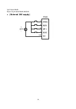
Page 18: ...16 type ring terminals Note Only for 202 203 401 402 403 z External 24V supply TM2 FWD REV SP1 RST 0V 3 4 6 7 10 24V...

Page 19: ...al refer to F_21 Connection point rated capacity 250VAC 1A 30VDC 1A 3 FWD FW 4 REV RE Operation control terminals refer to F_03 5 12V 12 Common point of terminal 3 4 6 7 6 SP1 SP 7 RESET RS Multifunct...

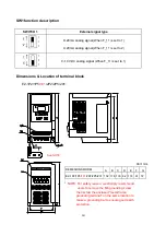
Page 20: ...o 1 Dimensions Location of terminal block E2 1P2 1P5 101 2P2 2P5 201 Unit mm DEMESIONS MODEL A B C D E F G E2 1P2 1P5 101 2P2 2P5 201 132 116 130 8 2 118 61 72 NOTE For safety reason we strongly recom...

Page 21: ...2 403 Dimensions Installation of class B Filter M 4 x 1 4 L M O D EL LEN G TH A 143 1127 5 B 140 C D 8 0 LEN G TH E2 202 203 401 402 403 M O D EL 171 7 E 108 F 118 G U ni t m m E2 202 203 401 402 403...

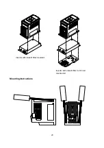
Page 22: ...20 Mounting Instructions Inverter with class B filter mounted Inverter with class B filter Din rail mounted kit...

Page 23: ...inverter Step2 Push the DIN Rail forward until the middle rib grips firmly with back panel Step1 Use a small screwdriver inserting it into the middle rib of DIN Rail and press the screwdriver in orde...

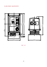
Page 24: ...22 E2 2P2 2P5 201 N4X IP65 TYPE UNIT mm STOP 0 1 R RUN ENT DATA FUN DSP RESET F 0 116 57 102 41 117 23 133 57 188 96 204 82 133 00 173 38...

Page 25: ...23 E2 202 203 401 402 403 N4X IP65 TYPE UNIT mm...

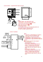
Page 26: ...nning signal before power on again after power supply interrupted Otherwise injury may result 3 PHASE IM L1 L2 T1 T2 T3 FW RE 12V 10V VI 0V POWER SWITCH REV 0 FWD SWITCH Potentiometer AC 200 240 50 60...

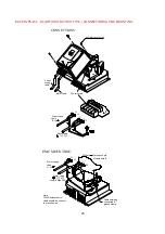
Page 27: ...Remote control cable should be connect to ground screw T3 L1 L2 T2 T1 L1 L2 T1 T2 T3 4 x Outer cover screw CONNECTIONS T1 T2 T3 Motor cable TM1 terminals Power supply cable L1 L2 Motor cable Power su...

Page 28: ...n terminals Power supply cable Motor cable EMCMOUNTIING Power supply cable L1 L2 Cutting Length of cable shield 200mm Cable shielding connected to ground clamp Note TM2 Remote control cable should be...

Page 29: ...oid damaging keypad Brief keypad operation flowchart Note 1 Displayed setting of frequency when stopped Display output frequency when running Note 2 The setting of the frequency can be modified either...

Page 30: ...0 Keypad 1 Terminal TM2 1 0 1 0 27 Frequency Control 11 0 Keypad 1 Terminal 0 10v 0 20mA 2 Terminal 4 20mA 1 0 2 0 28 Carrier frequency control 12 Carrier Frequency Setting 1 1 5 1 10 4 5 28 Torque co...

Page 31: ...28 0 enable 1 disable 1 0 1 1 34 5 Software version 29 CPU program version 35 Fault Log 30 Fault log for three faults 35 NOTE 1 Indicate this parameter can be adjusted during running mode 2 Please re...

Page 32: ...ting 0 Forward 1 Reverse Although there is no Forward Reverse push button on the digital control panel it is possible to adjust forward reverse function by changing the F_04 setting NOTE When F_22 1 R...

Page 33: ...ation High starting torque Decreasing torque F_5 1 2 3 V F pattern Specification 60Hz System Application General Application High starting torque Decreasing torque F_5 4 5 6 V F pattern F_5 B C 1 4 10...

Page 34: ...ltifunction input terminal is ON the inverter operates at sp1 frequency F_08 2 When F_19 or F_20 1 and the multifunction input terminal is ON the inverter operate at jog frequency F_09 3 The priority...

Page 35: ...4 kHz 5 8 kHz 9 15 kHz 1 2 5 kHz 6 10 kHz 1 10 16 kHz 1 3 6 kHz 7 12 kHz 1 4 7 2 kHz 8 14 4 kHz 1 NOTE 1 Available for CPU version V1 9 and above 2 If F_12 7 10 the inverter must operator with low lo...

Page 36: ...et frequency setup by F_16 after this the output voltage level that is set in the F_17 will determine the amount of DC voltage that s injected into the motor The time duration to perform this stopping...

Page 37: ...eeds the heat dissipation efficiency is lower The electronic thermal activation level is also reduced to change from curve 1 to curve 2 in Figure 3 Choose the appropriate F_05 setting according to the...

Page 38: ...ds to decelerate and stop ignoring the setting of F_14 The inverters E S light will flash after stopping After the emergency stop signal is deactivated turn the RUN switch OFF and then ON again to cyc...

Page 39: ...Speed Signal 3 F_21 3 Fault signal Terminal1 and2 of TM2 are activated at CPF OL1 OL2 OCS OCA OCC Ocd Ocb OVC LVC OHC Hz Time F_21 1 Terminal 1 2 on F_21 2 Terminal 1 2 on F_22 Reverse Lock Out 0 REV...

Page 40: ...ntary power loss is long the inverter must be restart manually The operation of the inverter is based on the setup of F_10 and the condition of external switch 4 When restart the inverter the operatio...

Page 41: ...cess is complete 50Hz operation 2 When F_25 is set to 020 all parameters are restored to factory settings The settings of F_05 4 and F_06 60 F_25 is restored back to 000 after the reset process is com...

Page 42: ...ed xxx Indicates the earliest malfunction in the record 2 After entering the F_30 function the x xx trip record will be displayed first After that press button and you can read activity in a chronolog...

Page 43: ...r supply 2 Return the inverter for repair Inverter over heat while not operating 1 Detection circuit defective 2 Environment over heat or poor ventilation 1 Return the inverter for repair 2 Improve ve...

Page 44: ...t side Over current at deceleration Deceleration setting too short Adjust to use a longer acceleration time Over current at breaking DC Breaking frequency breaking voltage or breaking time setting too...

Page 45: ...top signal is activated through the multi function input terminal the inverter decelerates and stops Inverter flashes E S after stops Refer to instruction for F_19 for detail External BASE BLOCK When...

Page 46: ...the output terminals T1 T2 and T3 correct z Operate by digital Motor operate in opposite direction Is the wiring for the forward and reverse signals correct z Wiring should be in accordance with the...

Page 47: ...ion indication is Any sign of burnt of breakage Is the primary circuitry DM normal Is the primary circuitry I G B T normal Replace defective board Is LED2 illuminate Is the DC input voltage of control...

Page 48: ...is out of order YES Carry out parameter initialization Designate operation control method Frequency instruction setting Does the controller displays frequency setting Is there voltage output on UVW t...

Page 49: ...B T Is the current detector normal NO YES NO ABNORMAL Is there any malfunction indication Input frequency setting Is there output voltage on UVW terminals Connect motor and proceed with operation Is t...

Page 50: ...on instruction Replace defective board NO NO Is there any malfunction indication Input frequency instruction Is there output voltage on T1 T2 and T3 terminals Connect motor Is the motor operating Is t...

Page 51: ...CCB Power source abnormality Poor wiring Place the operation switch to RUN position Is the T1 T2 T2 T3 T3 T1 output voltage in balance condition ABNORMAL NO YES YES When the motor is not connected and...

Page 52: ...tage level between T1 T2 T2 T3 and T3 T1 normal YES Operate at low speed for a long time Select another motor Remove obstacle affecting motor cooling Correct the connection NO YES YES E2 malfunction P...

Page 53: ...e load Increase E2 and motor capacity Reduce loading variation or install fly wheel Improve mechanical system NO YES YES E2 malfunction During acceleration or deceleration NO Is the voltage level betw...

Page 54: ...ircuitry normal Measure voltage by multi meter Voltage level conforming specification Improve input power source Is the tighten parts secured Is there any sign of breakage on the terminal panel Invert...

Page 55: ...eck out mounting screws on every terminal and parts Tighten loose screws 3 Dielectric strength test a Remove all conducting wires between Drive and outside world Power must be turned OFF b The dielect...

Page 56: ...Ii Moving iron Input power Pi Power meter P W1 Input power factor PFi Calculate power factor by the input voltage input current and input power Output voltage Vo Rectifier Moving iron not allowed Maxi...

Page 57: ...130 x 72 x 7 5 E2 1P2 1P5 101 2P2 2P5 201 E2 202 203 401 402 403 Specification of Braking Resister and Input Reactor Input AC Reactor MODEL Braking transistor build in Braking resister build in Torque...

Page 58: ...eight 5pc N W kg E2 202 Hxxx BRN2 202 1 5 150 100 10 119 215 40 20 325 225 70 5 2 1 E2 203 Hxxx BRN2 203 2 2 200 70 9 116 165 60 30 200 195 80 3 2 E2 401 H3xx BRN2 401 0 75 60 750 8 125 115 40 20 200...

Page 59: ...APPLICATION TELEPHONE ADDRESS F_ Value Setting F_ Value Setting F_ Value Setting F_00 F_11 F_22 F_01 F_12 F_23 F_02 F_13 F_24 F_03 F_14 F_25 F_04 F_15 F_26 F_05 F_16 F_27 F_06 F_17 F_28 F_07 F_18 F_29...

Page 60: ...Output Current A 1 4 2 3 4 2 7 5 10 5 Capacity KVA 0 53 0 88 1 6 2 9 4 0 Rated Weight Kg 0 76 0 77 0 8 1 66 1 76 Input Voltage Max Single Three phases 200 240V 10 15 50 60Hz 5 Output Voltage Max Three...

Page 61: ...icroprocessor Controlled IGBT Drive Inverter Motor Speed Regulator Operating Manual High Performance Adjustable Speed Micro Drives E2 Series 110V 0 2 0 75KW 0 53 1 6KVA 220V 0 2 2 2KW 0 53 4 0KVA 440V...

Page 62: ...ment 7 2 Sample Model No Identification 8 3 Specifications 9 4 Wiring 15 5 Dimensions Location of terminal block 18 Chapter 3 Software Index 1 Keypad Operating Instructions 27 2 Parameters List 28 3 P...

Page 63: ...turning off the power before the charging indicator went off z Do not attempt to wire circuitry while power is on Do not attempt to examine the components and signals on the PCB while the inverter op...

Page 64: ...verter z Check to see if the model number of the AC inverter matches the model number of the AC inverter that you ordered z Check to see whether any damage occurred to the AC inverter during shipment...

Page 65: ...injury or damage to the inverter itself z Install the inverter onto a firm metal base plate or another non flammable type material Do not install the inverter onto or nearby any flammable material z A...

Page 66: ...t the inverter still has enough storage power to control the circuit therefore when power is regenerated the inverter will automatically start operation again depends on the setup of F_23 When restart...

Page 67: ...Please reconfirm the operating range of motor and the machinery you are controlling z Do not examining the signals on the PCB of the inverter when it is under operation z All inverters are properly ad...

Page 68: ...vironments Keep away from rain or where dripping water may get into the inverter Avoid metal dust and dusty environments Avoid massive vibration Avoid excessive direct heat Avoid where environmental t...

Page 69: ...foreign dusts flocks or metal scraps from entering interior z Avoid electric magnetic interference soldering or power machinery z Avoid vibration if vibration cannot be avoided an anti rattle mounting...

Page 70: ...Power Voltage Horse Power Rated Model Type Power Supply Filter Option Enclosure Type Ventilation Installation Direction Front View 1 110V 2 220V 4 440V P2 0 25 Hp P5 0 5 Hp 01 1 Hp 02 2 Hp 03 3 Hp M C...

Page 71: ...Output Current A 1 4 2 3 4 2 7 5 10 5 Capacity KVA 0 53 0 88 1 6 2 9 4 0 Rated Weight Kg 0 76 0 77 0 8 1 66 1 76 Input Voltage Max Single Three phases 200 240V 10 15 50 60Hz 5 Output Voltage Max Three...

Page 72: ...ction Decelerate or free run stop Auto reset DC braking frequency Voltage Time can be setup by constants Display Three digital LED display frequency inverter parameter fault record program version Ope...

Page 73: ...mm2 Terminal screw M3 Wire dimension 14AWG 2 0m m2 Terminal screw M3 M4 Wire dimension 3 5mm2 Terminal screw M4 Wire dimension 3 5mm2 Terminal screw M4 Signal Terminal TM2 1 11 Wire dimension 0 75mm2...

Page 74: ...The Magnetic Contact can be omitted at ordinary operation To utilize external control automatic restart or breaking controller the magnetic contact must be added at the primary side z Do not operate t...

Page 75: ...ts and the shielding make contact with the frequency inverter and the motor z Don t solder a conductor to the shielding z Use a metal clamp to connect the shielding from the motor cable with the metal...

Page 76: ...be used to wire the control circuitry Please refer to following diagram Connect the shielding wire onto the grounding terminal Only connect one end of the shield Wiring distance must be under 50m C T...

Page 77: ...eter for primary power circuitry and control circuitry in accordance with electricity regulations Wiring Diagram Wire Terminations to the Inverter must be made with either UL listed field wiring lugs...

Page 78: ...16 type ring terminals Note Only for 202 203 401 402 403 z External 24V supply TM2 FWD REV SP1 RST 0V 3 4 6 7 10 24V...

Page 79: ...al refer to F_21 Connection point rated capacity 250VAC 1A 30VDC 1A 3 FWD FW 4 REV RE Operation control terminals refer to F_03 5 12V 12 Common point of terminal 3 4 6 7 6 SP1 SP 7 RESET RS Multifunct...

Page 80: ...o 1 Dimensions Location of terminal block E2 1P2 1P5 101 2P2 2P5 201 Unit mm DEMESIONS MODEL A B C D E F G E2 1P2 1P5 101 2P2 2P5 201 132 116 130 8 2 118 61 72 NOTE For safety reason we strongly recom...

Page 81: ...2 403 Dimensions Installation of class B Filter M 4 x 1 4 L M O D EL LEN G TH A 143 1127 5 B 140 C D 8 0 LEN G TH E2 202 203 401 402 403 M O D EL 171 7 E 108 F 118 G U ni t m m E2 202 203 401 402 403...

Page 82: ...20 Mounting Instructions Inverter with class B filter mounted Inverter with class B filter Din rail mounted kit...

Page 83: ...inverter Step2 Push the DIN Rail forward until the middle rib grips firmly with back panel Step1 Use a small screwdriver inserting it into the middle rib of DIN Rail and press the screwdriver in orde...

Page 84: ...22 E2 2P2 2P5 201 N4X IP65 TYPE UNIT mm STOP 0 1 R RUN ENT DATA FUN DSP RESET F 0 116 57 102 41 117 23 133 57 188 96 204 82 133 00 173 38...

Page 85: ...23 E2 202 203 401 402 403 N4X IP65 TYPE UNIT mm...

Page 86: ...nning signal before power on again after power supply interrupted Otherwise injury may result 3 PHASE IM L1 L2 T1 T2 T3 FW RE 12V 10V VI 0V POWER SWITCH REV 0 FWD SWITCH Potentiometer AC 200 240 50 60...

Page 87: ...Remote control cable should be connect to ground screw T3 L1 L2 T2 T1 L1 L2 T1 T2 T3 4 x Outer cover screw CONNECTIONS T1 T2 T3 Motor cable TM1 terminals Power supply cable L1 L2 Motor cable Power su...

Page 88: ...n terminals Power supply cable Motor cable EMCMOUNTIING Power supply cable L1 L2 Cutting Length of cable shield 200mm Cable shielding connected to ground clamp Note TM2 Remote control cable should be...

Page 89: ...oid damaging keypad Brief keypad operation flowchart Note 1 Displayed setting of frequency when stopped Display output frequency when running Note 2 The setting of the frequency can be modified either...

Page 90: ...0 Keypad 1 Terminal TM2 1 0 1 0 27 Frequency Control 11 0 Keypad 1 Terminal 0 10v 0 20mA 2 Terminal 4 20mA 1 0 2 0 28 Carrier frequency control 12 Carrier Frequency Setting 1 1 5 1 10 4 5 28 Torque co...

Page 91: ...28 0 enable 1 disable 1 0 1 1 34 5 Software version 29 CPU program version 35 Fault Log 30 Fault log for three faults 35 NOTE 1 Indicate this parameter can be adjusted during running mode 2 Please re...

Page 92: ...ting 0 Forward 1 Reverse Although there is no Forward Reverse push button on the digital control panel it is possible to adjust forward reverse function by changing the F_04 setting NOTE When F_22 1 R...

Page 93: ...ation High starting torque Decreasing torque F_5 1 2 3 V F pattern Specification 60Hz System Application General Application High starting torque Decreasing torque F_5 4 5 6 V F pattern F_5 B C 1 4 10...

Page 94: ...ltifunction input terminal is ON the inverter operates at sp1 frequency F_08 2 When F_19 or F_20 1 and the multifunction input terminal is ON the inverter operate at jog frequency F_09 3 The priority...

Page 95: ...4 kHz 5 8 kHz 9 15 kHz 1 2 5 kHz 6 10 kHz 1 10 16 kHz 1 3 6 kHz 7 12 kHz 1 4 7 2 kHz 8 14 4 kHz 1 NOTE 1 Available for CPU version V1 9 and above 2 If F_12 7 10 the inverter must operator with low lo...

Page 96: ...et frequency setup by F_16 after this the output voltage level that is set in the F_17 will determine the amount of DC voltage that s injected into the motor The time duration to perform this stopping...

Page 97: ...eeds the heat dissipation efficiency is lower The electronic thermal activation level is also reduced to change from curve 1 to curve 2 in Figure 3 Choose the appropriate F_05 setting according to the...

Page 98: ...ds to decelerate and stop ignoring the setting of F_14 The inverters E S light will flash after stopping After the emergency stop signal is deactivated turn the RUN switch OFF and then ON again to cyc...

Page 99: ...Speed Signal 3 F_21 3 Fault signal Terminal1 and2 of TM2 are activated at CPF OL1 OL2 OCS OCA OCC Ocd Ocb OVC LVC OHC Hz Time F_21 1 Terminal 1 2 on F_21 2 Terminal 1 2 on F_22 Reverse Lock Out 0 REV...

Page 100: ...ntary power loss is long the inverter must be restart manually The operation of the inverter is based on the setup of F_10 and the condition of external switch 4 When restart the inverter the operatio...

Page 101: ...cess is complete 50Hz operation 2 When F_25 is set to 020 all parameters are restored to factory settings The settings of F_05 4 and F_06 60 F_25 is restored back to 000 after the reset process is com...

Page 102: ...ed xxx Indicates the earliest malfunction in the record 2 After entering the F_30 function the x xx trip record will be displayed first After that press button and you can read activity in a chronolog...

Page 103: ...r supply 2 Return the inverter for repair Inverter over heat while not operating 1 Detection circuit defective 2 Environment over heat or poor ventilation 1 Return the inverter for repair 2 Improve ve...

Page 104: ...t side Over current at deceleration Deceleration setting too short Adjust to use a longer acceleration time Over current at breaking DC Breaking frequency breaking voltage or breaking time setting too...

Page 105: ...top signal is activated through the multi function input terminal the inverter decelerates and stops Inverter flashes E S after stops Refer to instruction for F_19 for detail External BASE BLOCK When...

Page 106: ...the output terminals T1 T2 and T3 correct z Operate by digital Motor operate in opposite direction Is the wiring for the forward and reverse signals correct z Wiring should be in accordance with the...

Page 107: ...ion indication is Any sign of burnt of breakage Is the primary circuitry DM normal Is the primary circuitry I G B T normal Replace defective board Is LED2 illuminate Is the DC input voltage of control...

Page 108: ...is out of order YES Carry out parameter initialization Designate operation control method Frequency instruction setting Does the controller displays frequency setting Is there voltage output on UVW t...

Page 109: ...B T Is the current detector normal NO YES NO ABNORMAL Is there any malfunction indication Input frequency setting Is there output voltage on UVW terminals Connect motor and proceed with operation Is t...

Page 110: ...on instruction Replace defective board NO NO Is there any malfunction indication Input frequency instruction Is there output voltage on T1 T2 and T3 terminals Connect motor Is the motor operating Is t...

Page 111: ...CCB Power source abnormality Poor wiring Place the operation switch to RUN position Is the T1 T2 T2 T3 T3 T1 output voltage in balance condition ABNORMAL NO YES YES When the motor is not connected and...

Page 112: ...tage level between T1 T2 T2 T3 and T3 T1 normal YES Operate at low speed for a long time Select another motor Remove obstacle affecting motor cooling Correct the connection NO YES YES E2 malfunction P...

Page 113: ...e load Increase E2 and motor capacity Reduce loading variation or install fly wheel Improve mechanical system NO YES YES E2 malfunction During acceleration or deceleration NO Is the voltage level betw...

Page 114: ...ircuitry normal Measure voltage by multi meter Voltage level conforming specification Improve input power source Is the tighten parts secured Is there any sign of breakage on the terminal panel Invert...

Page 115: ...eck out mounting screws on every terminal and parts Tighten loose screws 3 Dielectric strength test a Remove all conducting wires between Drive and outside world Power must be turned OFF b The dielect...

Page 116: ...Ii Moving iron Input power Pi Power meter P W1 Input power factor PFi Calculate power factor by the input voltage input current and input power Output voltage Vo Rectifier Moving iron not allowed Maxi...

Page 117: ...130 x 72 x 7 5 E2 1P2 1P5 101 2P2 2P5 201 E2 202 203 401 402 403 Specification of Braking Resister and Input Reactor Input AC Reactor MODEL Braking transistor build in Braking resister build in Torque...

Page 118: ...eight 5pc N W kg E2 202 Hxxx BRN2 202 1 5 150 100 10 119 215 40 20 325 225 70 5 2 1 E2 203 Hxxx BRN2 203 2 2 200 70 9 116 165 60 30 200 195 80 3 2 E2 401 H3xx BRN2 401 0 75 60 750 8 125 115 40 20 200...

Page 119: ...APPLICATION TELEPHONE ADDRESS F_ Value Setting F_ Value Setting F_ Value Setting F_00 F_11 F_22 F_01 F_12 F_23 F_02 F_13 F_24 F_03 F_14 F_25 F_04 F_15 F_26 F_05 F_16 F_27 F_06 F_17 F_28 F_07 F_18 F_29...

Page 120: ...Output Current A 1 4 2 3 4 2 7 5 10 5 Capacity KVA 0 53 0 88 1 6 2 9 4 0 Rated Weight Kg 0 76 0 77 0 8 1 66 1 76 Input Voltage Max Single Three phases 200 240V 10 15 50 60Hz 5 Output Voltage Max Three...

Page 121: ...China Tel 886 2 25111181 Fax 886 2 25633586 http taian electric com tw This manual may be modified when necessary because of improvement of product modification or change in specifications This inform...

Reviews: