


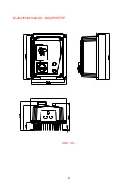


15
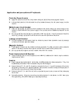
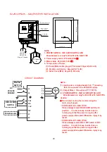
loads (such as soldering machines or large current motors). They should be grounded
separately.
z
Grounding circuitry must not be formed when grounding several inverters together.
(a) good (b) good
(c) not good
(D) Wire specification, apply appropriate wire with correct diameter for primary power circuitry and
control circuitry in accordance with electricity regulations.
Wiring Diagram
Wire Terminations to the Inverter must be made with either UL listed field wiring lugs or UL listed crimp
P R
L1 (L)
L2
L3 (N)
FWD
REV
SP1
RST
12V
+10V
MVI
(0~10V/0~20/4~20mA)
0V(FM–)
FM+
*(note)Braking
Resister (Option)
SW1
1
2
3
(U)T1
(V)T2
(W)T3
1
2
CON2
AC Input
IM
}
Trip Relay
Test Points
Grounding
3
4
6
7
5
{
Multi-Function
Inputs
8
9
10
11
FM
Speed Pot 10k
Ω
0~10V