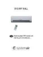


3. ATTACHED FITTINGS
Please check whether the following fittings are of full scope. If there are some spare fittings , please restore them carefully.
QUANTITY
SHAPE
NAME
3. Plastic expanded tube
5.Drain pipe
4. Wrapping tape
6. Wall conduit cover
11. Owner's manual
12. Installation manual
13.
Network matching wire
8. Frame
9. Mounting screw(ST2.9
10-C-H)
10. Alkaline dry batteries (AM4)
1. Remote controller manual
8
1
8
1
1
1
1
1
2
2
1
1
3
installation manual
FUNCTION
2. Screw ST3.9x25 for installation board
Secure the installation board
This manual
1
Hold the remote controller
7. Remote controller
(including operation manual)
Insulation Holder for remote controller
Fig.3-1
Never throw or beat the controller.
Before installation, operate the remote controller to determine its location in a
reception range.
Keep the remote controller at least 1m apart from the nearest TV set or stereo
equipment. (it is necessary to prevent image disturbances or noise interferences.)
Do not install the remote controller in a place exposed to direct sunlight or close to a
heating source, such as a stove.
Note that the positive and negative poles are right positions when loading batteries.
This manual is subject to changes due to technological improvement without further
notices.
Cautions on remote controller installation:
Remote controller
holder
Mounting screw B
ST2.9x10-C-H
Not attach in several unit
The indoor unit which at the terminal of
communication system should connect a
impedance between port P and port Q.
14.Copper nut
1
Connect piping
Remote
controller
ON OFF
MODE
FAN
SPEED
TURBO
LED DISPLAY
TEMP
SET
TIMER
ECO
DRY E•A•H FOLLOW ME
FAN DIRECTION
SYSCONTROL RM 02
AUTO
COOL
DRY
HEAT
FAN
TIMER OFF
TIMER ON
FOLLOW ME
TEMP
FAN SPEED
FAN SPEED
FOLLOW ME
FOLLOW ME
SLEEP
MODE


