background image

102/105 | 

S-BM2

Legend

Y1, Y2, Y3, Y4

 - Cutting plane

a)

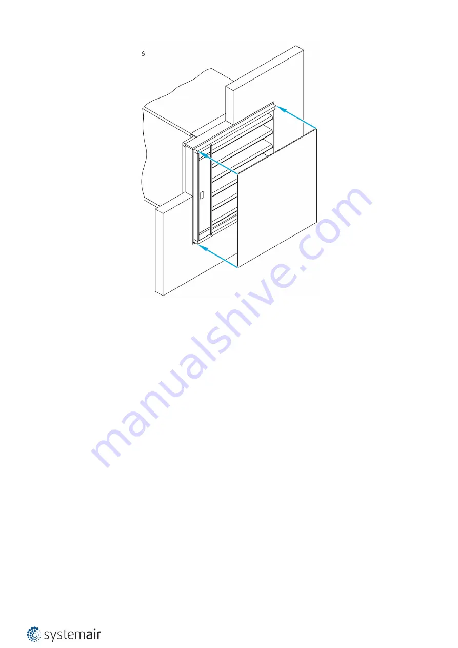
 - For wall installation - insert the filling as per desired installation.

b)

 - For duct installation – fix the hangers so that the weight of the damper is supported.

Operation Manual

After installation, it is necessary to adjust the damper into its operating position “closed”. In case, that the damper is 
used for extraction of pollutants, adjust the damper into its operating position “open”. 
Connect the actuator to the relevant electric power supply as per Electrical connections section. The actuator is 
activated and adjusts the damper into its operating position.

Warning

Some damper parts may have sharp edges; therefore, to protect yourself, please use gloves during damper installation 
and manipulation. In order to prevent electric shock, fire or any other damage which could result from incorrect 
damper usage and operation, it is important to:
1.Ensure that installation is performed by a trained person.
2.Follow the written and depicted instructions provided within this User Manual closely.
3.Perform damper inspection in accordance with this User Manual.
4.Check the damper’s functionality as per the “Smoke Damper Functionality Check” chapter before you install the 
smoke damper. This procedure prevents the installation of a damper that has been damaged during transportation or 
handling.

Summary of Contents for A-S-BM2

Page 1: ...S BM2 Smoke Control Damper MA multi ...

Page 2: ...2 105 S BM2 Table of Contents Overview 3 Technical Parameters 5 Diagrams 9 Dimensions 14 Ordering Code 21 Installation 22 Electrical parameters 86 Operation manual 99 ...

Page 3: ...rtments classified as multi Can be used also in compartments classified as single Pressure level 2 1000 Pa 300 Pa Casing leakage according to EN 1751 class C Blade leakage according to EN 1751 class 3 Exceptional free area and low pressure drop Installed into walls or ducts Fire Resistivity S BM2 Smoke control dampers are CE certified following the Construction Products Regulation according to EN ...

Page 4: ...he damper is ordered with grille both sides are fitted with threaded inserts for grille placement S BM2 has mechanism and actuator enclosed by the dampers casing and two covers on each side for easy access and connection Material Composition The product contains galvanized sheet metal calcium silicate board fireproof carbon fiberglass polyurethane foam and alkaline earth silicate wool These are pr...

Page 5: ...Max 12 m s Side with Fire Protection Depending on installation classification From both sides i o Repeated Opening Suitable for daily check procedure in suitable environment Closing Opening Time 60 s Indicator Closed Open Indication with microswitches that are part of mechanism actuator Environment Suitability Only indoor environment T 0 C and Rha 95 3K5 according to EN 60721 3 3 Inspection Possib...

Page 6: ...S Machinery Directive 2014 35 EU Low Voltage Directive 2014 30 EU Electromagnetic Compatibility Directive Driving Actuator Types Belimo BEN24 BEN230 BEN24 ST BEN24 SR BEE24 BEE230 BEE24 ST BEE24 SR BE24 BE230 BE24 ST BLE24 BLE230 BLE24 ST Transport and Storage Dry indoor conditions with a temperature range of 20 C to 50 C The damper blade is transported in closed position ...

Page 7: ...zes also includes wooden manipulation jig Legend P1 Damper casing P2 Damper blade P3 Actuator P4 Supply and communication unit BST P5 Sheet metal Grille P6 Threaded inserts for duct connection P7 Threaded inserts for the grille P8 Mechanism cover P9 Product label ...

Page 8: ...time and in allowable time Response delay closure time Manual intervention passed Operational reliability 10 000 operations 0 to 90 passed and 45 to 60 passed HOT 400 30 passed Fire resistance Integrity E EI120 vew ved hod how i o S1000CmodHOT400 30MAmulti Damper with vertically oriented blades EI90 vewi o S1000CmodMAmulti Insulation I Smoke leakage S Mechanical stability under E Maintenance of cr...

Page 9: ...45 50 55 60 65 70 75 S BM2 00 Pressure drop A weighted sound power level in dB A 5000 10000 50000 m h 1000 5000 10000 l s 5 10 50 Pa W 500 H 625 W 800 H 825 W 1000 H 1225 40 45 50 55 60 65 70 75 80 45 50 55 60 65 70 75 80 85 90 50 55 60 65 70 75 80 85 S BM2 01 Pressure drop A weighted sound power level in dB A 500 1000 5000 m h 100 500 1000 l s 5 10 50 100 Pa W 125 H 325 W 200 H 325 W 300 H 425 25...

Page 10: ... 45 50 55 60 65 70 75 80 85 S BM2 11 Pressure drop A weighted sound power level in dB A 5000 10000 50000 m h 1000 5000 10000 l s 5 10 50 100 Pa W 500 H 625 W 800 H 825 W 1000 H 1225 25 30 35 40 45 50 55 60 65 70 75 80 85 25 30 35 40 45 50 55 60 65 70 75 80 85 90 95 25 30 35 40 45 50 55 60 65 70 75 80 85 90 Legend ps Pa Pressure drop qv m3 h l s Air flow volume Δ Deviation from measured value Lwa d...

Page 11: ...0 45 50 55 60 65 70 75 80 85 45 50 55 60 65 70 75 80 85 90 45 50 55 60 65 70 75 80 85 90 S BM2 M0 Pressure drop A weighted sound power level in dB A 20000 50000 100000 m h 5000 10000 20000 l s 5 10 50 Pa W 800 H 2330 W 1000 H 2530 50 55 60 65 70 75 80 85 90 50 55 60 65 70 75 80 85 90 Legend ps Pa Pressure drop qv m3 h l s Air flow volume Δ Deviation from measured value Lwa dB A A weighted total so...

Page 12: ...5 50 55 60 65 70 75 80 85 40 45 50 55 60 65 70 75 80 85 90 45 50 55 60 65 70 75 80 85 90 S BM2 M0 Pressure drop A weighted sound power level in dB A 20000 50000 100000 m h 5000 10000 20000 l s 5 10 50 Pa W 1880 H 1025 W 2080 H 1225 50 55 60 65 70 75 80 85 90 50 55 60 65 70 75 80 85 90 Legend ps Pa Pressure drop qv m3 h l s Air flow volume Δ Deviation from measured value Lwa dB A A weighted total s...

Page 13: ...0 65 70 75 80 85 90 50 55 60 65 70 75 80 85 90 95 50 55 60 65 70 75 80 85 90 95 S BM2 M0 Pressure drop A weighted sound power level in dB A 20000 50000 100000 200000 m h 10000 20000 50000 l s 5 10 50 Pa W 1880 H 2130 W 2080 H 2530 55 60 65 70 75 80 85 90 95 55 60 65 70 75 80 85 90 95 Legend ps Pa Pressure drop qv m3 h l s Air flow volume Δ Deviation from measured value Lwa dB A A weighted total so...

Page 14: ...7 0 122 0 146 0 170 0 195 0 219 0 244 0 268 0 292 0 317 0 341 0 365 0 390 0 414 0 438 0 463 0 487 0 042 0 050 0 067 0 084 0 101 0 118 0 134 0 151 0 168 0 185 0 202 0 218 0 235 0 252 0 269 0 286 0 302 0 319 0 336 825 0 081 0 097 0 129 0 162 0 194 0 226 0 259 0 291 0 324 0 356 0 388 0 421 0 453 0 485 0 518 0 550 0 582 0 615 0 647 0 056 0 067 0 089 0 112 0 134 0 156 0 179 0 201 0 223 0 246 0 268 0 29...

Page 15: ... 3 63 1 64 9 35 4 36 4 38 3 40 2 42 1 44 0 46 0 47 9 49 8 51 7 53 6 55 5 57 4 59 4 61 3 63 2 65 1 67 0 69 0 825 39 1 40 1 42 1 44 0 45 9 47 9 49 8 51 8 53 7 55 7 57 6 59 6 61 5 63 5 65 4 67 3 69 3 71 2 73 2 41 2 42 3 44 4 46 5 48 6 50 7 52 8 54 9 57 0 59 1 61 2 63 3 65 4 67 5 69 6 71 7 73 8 75 9 78 1 43 3 44 5 46 7 49 0 51 2 53 5 55 8 58 0 60 3 62 6 64 8 67 1 69 3 71 6 73 9 76 1 78 4 80 7 82 9 102...

Page 16: ...16 105 S BM2 Dimensions of grille type M0 M1 in battery type assembly ...

Page 17: ... 0 85 0 89 1930 0 29 0 36 0 44 0 51 0 58 0 65 0 73 0 80 0 87 0 95 1 02 1 09 1 16 1 24 1 31 1 38 1 45 0 20 0 25 0 30 0 35 0 40 0 45 0 50 0 55 0 60 0 65 0 70 0 75 0 80 0 85 0 90 0 95 1 00 2130 0 32 0 40 0 48 0 56 0 65 0 73 0 81 0 89 0 97 1 05 1 13 1 21 1 29 1 37 1 45 1 53 1 61 0 22 0 28 0 33 0 39 0 45 0 50 0 56 0 61 0 67 0 72 0 78 0 84 0 89 0 95 1 00 1 06 1 11 2330 0 35 0 44 0 53 0 62 0 71 0 80 0 89...

Page 18: ...GT M0 M1 A V m 2 W mm 1180 1230 1280 1330 1380 1430 1480 1530 1580 1630 1680 1730 1780 1830 1880 1930 1980 2030 2080 H mm 1530 1 25 1 30 1 36 1 42 1 47 1 53 1 59 1 64 1 70 1 76 1 81 1 87 1 93 1 98 2 04 2 10 2 15 2 21 2 27 0 86 0 90 0 94 0 98 1 02 1 06 1 10 1 13 1 17 1 21 1 25 1 29 1 33 1 37 1 41 1 45 1 49 1 53 1 56 1730 1 42 1 49 1 55 1 62 1 68 1 75 1 81 1 88 1 94 2 01 2 07 2 14 2 20 2 26 2 33 2 3...

Page 19: ...146 9 152 0 157 1 162 2 167 2 174 4 179 5 184 6 189 6 194 7 199 8 122 8 128 3 133 8 139 3 144 8 150 3 155 8 161 3 166 8 172 3 177 8 185 3 190 8 196 4 201 8 207 3 212 8 GT M0 M1 m kg W mm 1180 1230 1280 1330 1380 1430 1480 1530 1580 1630 1680 1730 1780 1830 1880 1930 1980 2030 2080 H mm 425 72 7 74 1 75 4 76 8 78 1 79 5 80 8 82 2 83 5 84 9 86 2 87 6 88 9 90 3 91 6 93 0 94 3 95 7 97 0 77 2 78 7 80 1...

Page 20: ... 2 321 4 259 0 263 5 268 0 272 6 277 1 281 6 286 1 290 7 295 2 299 7 304 3 308 8 313 4 318 9 324 4 328 9 333 5 338 0 342 6 2130 265 3 269 8 274 3 278 8 283 3 287 8 292 2 296 7 301 2 305 7 310 2 314 7 319 2 325 7 332 1 336 6 341 2 345 6 350 1 281 5 286 3 291 2 296 1 300 9 305 8 310 6 315 4 320 3 325 1 330 0 334 9 339 8 346 6 353 4 358 3 363 2 368 0 372 9 2330 284 7 289 5 294 3 299 1 303 9 308 6 313...

Page 21: ...rille on both sides RAL 9003 M0 Battery dimensions without Grille M1 Battery dimensions with Grille on one side Zinc connection for duct available on either side B Type of Activation B230 230V AC Belimo Actuator B24 24V AC DC Belimo Actuator B24 W 24V AC DC Belimo Actuator Wire connector for communication unit B24 SR 24V AC DC Belimo Actuator modulated 0 10V BST 230V AC Supply comm unit 24V AC DC ...

Page 22: ... 2 Dry S BM2 125 325 1000 1225 EI 120 vew i o S1000Cmod HOT400 30 MAmulti a 125 b 125 EI 90 vew i o S1000Cmod MAmulti a 125 b 125 3 Soft S BM2 125 325 1000 1225 EI 90 vew i o S1000Cmod HOT400 30 MAmulti b 125 EI 90 vew i o S1000Cmod MAmulti b 125 S BM2 W 1000 H 1225 2080 2530 EI 90 vew i o S1000Cmod HOT400 30 MAmulti b 125 S BM2 125 325 1000 1225 EI 120 how i o S1000Cmod HOT400 30 MAmulti c 125 62...

Page 23: ...on DMH DMV In the Metal duct installation D1H D2H Horizontally Oriented Damper On the Duct D1V D2V Vertically Oriented Damper On the Duct a Flexible plasterboard wall b Concrete masonry cellular concrete rigid wall c Concrete cellular concrete rigid floor ceiling d Duct per EN 1366 9 or EN 1366 8 vew Wall placement vertically oriented damper how Wall placement horizontally oriented damper ved Duct...

Page 24: ... being installed into or onto the duct Lists of all permitted installation methods are provided in Handbook Installation Maintenance Operation Some damper parts may have sharp edges therefore to protect yourself from harm please use gloves during damper installation and manipulation In order to prevent electric shock fire or any other damage which could result from incorrect damper usage and opera...

Page 25: ...he damper with gypsum plaster or mortar or concrete filling F1 while paying attention to prevent the fouling of the damper s functional parts which could limit its correct functionality The best way is to cover the functional parts during installation To prevent seepage of the filling material use of boards is recommended First let the plaster or mortar or concrete filling harden and then perform ...

Page 26: ...26 105 S BM2 ...

Page 27: ...27 105 S BM2 ...

Page 28: ...28 105 S BM2 ...

Page 29: ...29 105 S BM2 Opening and wall ceiling preparations ...

Page 30: ...30 105 S BM2 Damper minimum distances ...

Page 31: ...e 5 Grille 7 Connected sheet metal ductwork tested according to EN 1366 8 or EN 1366 9 F1 Plaster mortar concrete filling F4 Nails or pins per ductwork manufacturer instructions F5 Fire resistive coating Promat K84 Promat F8 Screw M8 35 maximum fixing torque is 8 Nm 12 Nm F11 Screw M5 100 mm to concrete Screw M4 5 120 mm to cellular concrete F12 Screw M5 60 70 mm e g DIN 7982 a If connected to a d...

Page 32: ...32 105 S BM2 Battery Installation Grille type M0 M1 ...

Page 33: ...33 105 S BM2 ...

Page 34: ...34 105 S BM2 Fixing layout for battery installations ...

Page 35: ...35 105 S BM2 Opening and wall ceiling preparations Damper minimum distances ...

Page 36: ... 9 F1 Plaster mortar concrete filling F4 Nails or pins per ductwork manufacturer instructions F5 Fire resistive coating Promat K84 Promat F8 Screw M8 35 maximum fixing torque is 8 Nm 12 Nm F11 Screw M5 100 mm to concrete Screw M4 5 120 mm to cellular concrete F12 Screw M5 60 70 mm e g DIN 7982 a If connected to a duct please follow the instructions duct manufacturer maximum duct size width height ...

Page 37: ...amper with gypsum plaster or mortar or concrete filling F1 while paying attention to prevent the fouling of the damper s functional parts which could limit its correct functionality The best way is to cover the functional parts during installation To prevent seepage of the filling material use of boards is recommended 7 First let the plaster or mortar or concrete filling harden before removing the...

Page 38: ...38 105 S BM2 ...

Page 39: ...39 105 S BM2 ...

Page 40: ...40 105 S BM2 ...

Page 41: ...41 105 S BM2 Opening and wall ceiling preparations Damper minimum distances ...

Page 42: ...ite using 3 mm sheet metal plate For sizes W 550 H 425 use 1 piece on each damper edge Total 4 pcs for each side of wall For sizes bigger than W 550 H 425 use 2 piece on each damper edge Total 8 pcs for each side of wall F1 Plaster mortar concrete filling F4 Nails or pins per ductwork manufacturer instructions F5 Fire resistive coating Promat K84 Promat F8 Screw M8 35 maximum fixing torque is 8 Nm...

Page 43: ...ith mineral wool F2 with a density of at least 100 kg m3 thoroughly but in such a way that will not deform the duct damper 4 Cover the gap filling between the damper and the mounting opening with gypsum boards 6 with applied coating F7 and fix them with screws F6 to the wall 5 Damper connections to duct and connection with overlap boards must be filled with coating F5 6 Check the functionality of ...

Page 44: ...44 105 S BM2 ...

Page 45: ...45 105 S BM2 ...

Page 46: ...46 105 S BM2 ...

Page 47: ...47 105 S BM2 Opening and wall ceiling preparations ...

Page 48: ...48 105 S BM2 Damper minimum distances ...

Page 49: ...terboard fireproof plate type F EN 520 4b Vertical CW profiles 4c Horizontal UW profiles 4d Mineral wool thickness cubic density see picture 5 Grille 6 Gypsum boards F2 Mineral wool filling min 100 kg m F4 Nails or pins per ductwork manufacturer instructions F5 Fire resistive coating Promat K84 Promat F6 Screws for fixing gypsum boards to flexible wall TN 3 5 35 rigid wall HUS CR 8 65 F7 Putty for...

Page 50: ... F5 between them and fix together with screws F12 and to the wall with screws F11 as depicted in fixing layout 3 Fill in the area between the wall and the damper with mineral wool F2 with a density of at least 100 kg m3 thoroughly but in such a way that will not deform the duct damper 4 All the gaps around the filling and ceiling surface area at least 40 mm from the damper body must be covered by ...

Page 51: ...51 105 S BM2 ...

Page 52: ...52 105 S BM2 ...

Page 53: ...53 105 S BM2 Opening and wall ceiling preparations Damper minimum distances ...

Page 54: ...sheet metal ductwork tested according to EN 1366 8 or EN 1366 9 F2 Mineral wool filling min 100 kg m F4 Nails or pins per ductwork manufacturer instructions F5 Fire resistive coating Promat K84 Promat F8 Screw M8 35 maximum fixing torque is 8 Nm 12 Nm F10 Fireproof coating HILTI CSF CT min 2 mm F11 Screw M5 100 mm to concrete Screw M4 5 120 mm to cellular concrete F12 Screw M5 60 70 mm e g DIN 798...

Page 55: ...55 105 S BM2 Battery Installation Grille type M0 M1 ...

Page 56: ...56 105 S BM2 ...

Page 57: ...57 105 S BM2 Fixing layout for battery installations ...

Page 58: ...58 105 S BM2 Opening and wall ceiling preparations Damper minimum distances ...

Page 59: ... Connected sheet metal ductwork tested according to EN 1366 8 or EN 1366 9 F2 Mineral wool filling min 100 kg m F4 Nails or pins per ductwork manufacturer instructions F5 Fire resistive coating Promat K84 Promat F8 Screw M8 35 maximum fixing torque is 8 Nm 12 Nm F10 Fireproof coating HILTI CSF CT min 2 mm F11 Screw M5 100 mm to concrete Screw M4 5 120 mm to cellular concrete F12 Screw M5 60 70 mm ...

Page 60: ... damper with at least 6 screws per each hanger 6 Fill in the area between the ceiling and the damper with mineral wool F2 with a density of at least 100 kg m3 thoroughly but in such a way that will not deform the body of the damper 7 All the gaps around the filling and ceiling surface area at least 100 mm from the damper body must be covered by fire resistive coating F10 8 Damper connections to du...

Page 61: ...61 105 S BM2 ...

Page 62: ...62 105 S BM2 ...

Page 63: ...63 105 S BM2 ...

Page 64: ...64 105 S BM2 Opening and wall ceiling preparations Damper minimum distances ...

Page 65: ...tal plate For sizes W 550 H 425 use 1 piece on each damper edge Total 4 pcs for each side of wall For sizes bigger than W 550 H 425 use 2 pieces on each damper edge Total 8 pcs for each side of wall F2 Mineral wool filling min 100 kg m F4 Nails or pins per ductwork manufacturer instructions F5 Fire resistive coating Promat K84 Promat F8 Screw M8 35 maximum fixing torque is 8 Nm 12 Nm F10 Fireproof...

Page 66: ...tal profile 4b on the remaining side with mineral wool segment F2 7 Place a mineral wool segment F2 on top of the damper and cover it with horizontal metal profile 4c 8 Fix the profile with screws F9 through the mineral wool segment to the damper and then on both sides to the wall vertical profiles 9 Cover both sides with 2 layers of gypsum boards 4a on each side without a gap between the damper a...

Page 67: ...67 105 S BM2 ...

Page 68: ...68 105 S BM2 ...

Page 69: ...69 105 S BM2 Opening and wall ceiling preparations ...

Page 70: ...ceiling 4 Flexible plasterboard wall 4a 2 layers of plasterboard fireproof plate type F EN 520 4b Vertical CW profiles 4c Horizontal UW profiles 4d Mineral wool thickness cubic density see picture 5 Grille F2 Mineral wool filling min 100 kg m F4 Nails or pins per ductwork manufacturer instructions F5 Fire resistive coating Promat K84 Promat F9 Self tapping screw size 4 length 45 mm e g DIN 7981 C ...

Page 71: ...r and ductwork with nails or pins as per duct system manufacturer instructions IMPORTANT The suspension of the damper must be loaded only with the weight of the damper Suspension systems longer than 1 5 m require fire resistant insulation The interior of the S BM2 smoke control damper must remain accessible for maintenance it may be necessary to create additional inspection panels in the connectin...

Page 72: ...72 105 S BM2 ...

Page 73: ... m3 Promat F4 Nails or pins per ductwork manufacturer instructions F5 Fire resistive coating Promat K84 Promat A1 Accessory K1 S BM2 W H size of damper W nominal width H nominal height A2 Hanger accessory H1 S BM2 can be made on site using 3 mm sheet metal plate For sizes W 550 or H 425 use 2 pieces on two damper edge Total 4 pcs For sizes bigger than W 550 or H 425 use 3 pieces on each damper edg...

Page 74: ...uspension systems longer than 1 5 m require fire resistant insulation The forces from thermal expansion of the duct must be avoided using flexible connections or duct bends The interior of the S BM2 smoke control damper must remain accessible for maintenance it may be necessary to create additional inspection panels in the connecting ducts The fire resistivity of S BM2 smoke control damper must be...

Page 75: ...75 105 S BM2 ...

Page 76: ...sory H1 S BM2 can be made on site using 3 mm sheet metal plate For sizes W 550 or H 425 use 2 pieces on two damper edge Total 4 pcs For sizes bigger than W 550 or H 425 use 3 pieces on each damper edge Total 6 pcs F3 Mineral wool filling thickness of mineral wool t depends on the desired fire resistivity F4 Nails or pins per ductwork manufacturer instructions F5 Fire resistive coating Promat K84 P...

Page 77: ... Apply fire resistive coat F5 on the connection surfaces 3 Place the damper on the profile hanger 4 Connect the damper to ductwork with boards 8 create collars and overlap the connection 5 Fix the collar covering to the damper and ductwork with nails or pins F4 as per duct system manufacturer instructions IMPORTANT The suspension of the damper must be loaded only with the weight of the damper Dime...

Page 78: ...78 105 S BM2 ...

Page 79: ...79 105 S BM2 ...

Page 80: ...t 5 Grille 8 Cover plate made of Promatect min 500 kg m3 Promat A2 Hanger accessory H1 S BM2 can be made on site using 3 mm sheet metal plate For sizes W 550 or H 425 use 2 pieces on two damper edge Total 4 pcs For sizes bigger than W 550 or H 425 use 3 pieces on each damper edge Total 6 pcs F4 Nails or pins per ductwork manufacturer instructions F5 Fire resistive coating Promat K84 Promat X Y Cut...

Page 81: ... Connect the damper to ductwork with boards 8 create collars and overlap the connection 5 Fix the collar covering to the damper and ductwork with nails or pins F4 as per duct system manufacturer instructions IMPORTANT The suspension of the damper must be loaded only with the weight of the damper Dimension of opening must be created according to details of each type and thickness of connected duct ...

Page 82: ...82 105 S BM2 ...

Page 83: ...83 105 S BM2 ...

Page 84: ...84 105 S BM2 ...

Page 85: ... 5 Grille 8 Cover plates made of Promatect min 500 kg m3 Promat A2 Hanger accessory H1 S BM2 can be made on site using 3 mm sheet metal plate For sizes W 550 or H 425 use 2 pieces on two damper edge Total 4 pcs For sizes bigger than W 550 or H 425 use 3 pieces on each damper edge Total 6 pcs F4 Nails or pins per ductwork manufacturer instructions F5 Fire resistive coating Promat K84 Promat X Y Cut...

Page 86: ... S BM2 Electrical Connections IMPORTANT Danger of electric shock Switch off the power supply before working on any electrical equipment Only qualified electricians are allowed to work on the electrical system ...

Page 87: ...87 105 S BM2 ...

Page 88: ...88 105 S BM2 ...

Page 89: ...89 105 S BM2 ...

Page 90: ...90 105 S BM2 ...

Page 91: ... and communication wires through the drilled holes 4 Fix the wire to avoid any damage from pulling from the outside 5 10 Connect the wires to the actuator or to the supply and communication unit 6 8 11 13 Caulk all wire crossings properly 7 12 Route the wires inside the mechanism so that there will be no damage to them from the moving mechanism 9 Close the mechanism lid and fix with screws ...

Page 92: ...0 3 0 3 6 5 Imax 8 2 A 5 ms BEE24 SR 25 AC DC 24 50 60 3 0 3 5 5 Imax 8 2 A 5 ms BST BEN24 ST BKNE230 24 15 AC 230 50 60 10 0 1 19 Imax 8 2 A 5 ms BEE24 ST BKNE230 24 25 AC DC 24 50 60 10 0 1 19 Imax 8 2 A 5 ms BE24 ST BKNE230 24 40 AC DC 24 50 60 12 0 5 18 Imax 8 2 A 5 ms Actuator size map of S BM2 B W mm 125 150 200 250 300 350 400 450 500 550 600 650 700 750 800 850 900 950 1000 H mm 325 425 62...

Page 93: ...93 105 S BM2 B 1180 1230 1280 1330 1380 1430 1480 1530 1580 1630 1680 1730 1780 1830 1880 1930 1980 2030 2080 1530 1730 1930 2130 2330 2530 ...

Page 94: ...EN When power supply is connected to wires 1 and 2 actuator drives to position CLOSED Notes Caution Main power supply voltage Parallel connection of several actuators possible Power consumption and switching thresholds must be observed Legend for activation type B230 1 blue 2 brown 3 white S1 violet S2 red S3 white S4 orange S5 pink S6 grey Belimo BE230 actuator has wires without colors ...

Page 95: ...PEN When power supply is connected to wires 1 and 2 actuator drives to position CLOSED Notes Caution Main power supply voltage Parallel connection of several actuators possible Power consumption and switching thresholds must be observed Legend for activation type B24 1 black 2 red 3 white S1 violet S2 red S3 white S4 orange S5 pink S6 grey Belimo BE24 actuator has wires without colors ...

Page 96: ...N When power supply is connected to wires 1 and 2 actuator drives to position CLOSED Legend for activation type B24 W The actuator is fitted with connection plugs Supply With 3 pole plug suitable for e g BKNE230 24 Auxiliary switch 6 pole plug suitable for e g BKNE230 24 Notes Caution Main power supply voltage Parallel connection of several actuators possible Power consumption and switching thresh...

Page 97: ...or drives to position CLOSED Legend for activation type B24 SR 1 black 2 red 3 white 5 orange S1 violet S2 red S3 white S4 orange S5 pink S6 grey Belimo BE24 actuator not available in SR configuration Notes Caution Main power supply voltage Parallel connection of several actuators possible Power consumption and switching thresholds must be observed Operating range Y DC 0 2 10 V Input Impedance 100...

Page 98: ...actuator to the desired position Two LEDs in the device indicate the function status LED Status Function Yellow Flashing Damper moves OPEN Yellow On Damper OPEN Green Flashing Damper moves CLOSED Green On Damper CLOSED Yellow and Green Flashing at double frequency Fault Yellow and Green Off Power failure Legend for activation type BST L brown N blue 1 Supply voltage cable 2 2 wire cable a b Connec...

Page 99: ... place the holder between the upper most blade and the frame 3 Carefully lift the smoke control damper with the forklift crane 4 Prepare the opening damper hanger connection surfaces and or filling as per the desired installation type 5 Place the smoke control damper in the opening wall installation or on the opening duct installation 6 Once the smoke control damper has been placed fix the damper ...

Page 100: ...100 105 S BM2 ...

Page 101: ...101 105 S BM2 ...

Page 102: ...the damper into its operating position Warning Some damper parts may have sharp edges therefore to protect yourself please use gloves during damper installation and manipulation In order to prevent electric shock fire or any other damage which could result from incorrect damper usage and operation it is important to 1 Ensure that installation is performed by a trained person 2 Follow the written a...

Page 103: ...d under the identical conditions as apply to the above mentioned six month inspections On its external side the damper housing and the actuator movement are checked Due to the need to perform a visual check of the damper s internal parts it is possible to dismount the body extension fitted with the grille which will enable access inside the damper or open the inspection lid if the damper is equipp...

Page 104: ...specifications contained herein and the terms should be discussed with the manufacturer We reserve the right to make any changes to the product without prior notice provided that these changes do not affect the quality of the product and the required parameters ...

Page 105: ...Systemair DESIGN 2021 06 29 Handbook_S_BM2_en GB ...

Reviews: