9.1.2
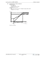
Diagram: setting signal and speed
nM
50 %
100 %
0
1
2
3
4
5
6
7
8
9
10
10
9
8
7
6
5
4
3
2
1
0
0
2
4
6
8
10
12
14
16
18
20
20
18
16
14
12
10
8
6
4
2
0
4
5,6
7,2
8,8
10,4
12
13,6 15,2 16,8 18,4
20
20
18,4 16,8 15,2 13,6
12
10,4
8,8
7,2
5,6
4
0 – 10 V
10 – 0 V
0 – 20 mA
20 – 0 mA
4 – 20 mA
20 – 4 mA
Min.
Min. 0 %
Max. = 100 %
Min. 35 %
Max. = 85 %
05.02.2008
v_nmotor_101_miluab.vsd
Si
Idealized principle diagram
nM
Motor speed
Si
Signal
9.1.3
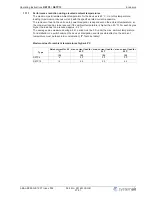
Operation with two variable output voltages (two steps)
DIP2 =
|
OFF
|
for setting via external signall.
Switchover between two steps via external potential-free contact possible.
•
Step 1
(low speed). When there is no input signal connected to the input terminal
“
E1
”
, then the
unit supplies the output voltage set by
“
n-min
”
.
•
Step 2
(high speed). When the terminal
“
A1
”
(+10 V) is connected with the input terminal
“
E1
”
then the units supplies the output voltage set by
“
n-max
”
.
n-min
nM
100 %
1
t
n-max
1
2
05.02.2008
v_diagr_2stufen.VSD
"A1" (+10 V)
"E1"
nMotor
= "n-max"
nMotor
= "n-min"
1
2
05.02.2008
v_schalter_2stufen.VSD
Operating Instructions
RETP6 / RETP10
Setting for operation
L-BAL-E082-GB 1237 Index 002
Part.-No. 00163339-GB
18/31


