5.9.1
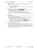
Enable, device ON / OFF
Electronic disconnection and Reset after motor fault via
fl
oating contact at terminals
“
D1
”
-
“
D1
”
•
Device
“
ON
”
for closed contact.
•
Device
“
OFF
”
with opened contact.
•
Relais
“
K1
”
remains energized, terminals 11 - 14 bridged. The signal lamp
fl
ashes in code
|
1
|
(
Diagnostics / faults)
5.9.2
Reverse action of control function (only for P-Controller / PI-Controller)
For operation as P-Controller or PI-Controller
2.01
,
3.01
,
4.01
. Digital input can used instead for
enable, alternative for reverse of control function (DIP 8 =
|
ON
|
).
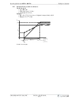
For the effect of the regulation there are two functions:
•
“
Val > Set = n+
”
increasing modulation for increasing actual value over setpoint.
•
“
Val < Set = n+
”
increasing modulation for decreasing actual value below setpoint.
When terminals
“
D1
”
-
“
D1
”
bridged, the device works with the opposite function than the one set with
DIP 4!
5.10
Relay output (K1)
An external fault indicator is available over the potential-free contacts of the built-in relay (max. contact
rating
Technical data and connection diagram).
For operation the relay is energized, terminals
“
12
”
and
“
14
”
are bridged. For fault the relay is de-
energized, terminals
“
11
”
and
“
12
”
are bridged (
Diagnostics / faults).
•
Fault indicated for: line fault, blown internal semiconductor fuse, broken controller-internal
voltage supply, overheating by the motor (thermostats
“
TB
”
connected).
•
By sensor failure (only in P-Control or PI-Control operation
2.01
,
3.01
,
4.01
) message only via
fl
ash code of signal lamp (code
|
3
|
), the relay remains energized.
•
When switching off via enable (D1 = Digital In 1), the relay remains energized.
5.11
Potential at control voltage connections
The control voltage connections (< 50 V) relate to the joint GND potential (Exception: Relay contacts
are potential free). There is a potential separation between the control voltage connections and the
protective earth. It must be ensured that the maximum external voltage at the control voltage
connections cannot exceed 50V (between
“
GND
”
terminals and
“
PE
”
protective earth). If necessary, a
connection to the protective earth potential can be established, install bridge between
“
GND
”
terminal
and the
“
PE
”
connection (terminal for screening).
Operating Instructions
RETP6 / RETP10
Electrical installation
L-BAL-E082-GB 1237 Index 002
Part.-No. 00163339-GB
11/31


