pag.
4
Industrial PC - MONITOR COPILOT 21,5"
Order Code 2E000xxx
May 2018 - Rev. 1.1
4.2 Installation in the hanging
version (VESA100)
To properly mount the
Copilot 21.5" Monitor
in the
VESA100 arm-mounted version follow the instructions
below:
-
Remove the
Copilot 21.5" Monitor
from its
packaging and place it on a flat surface free of objects,
placing a soft cloth on the table itself to avoid scratching
the glass during installation.
-
Place the
Copilot 21.5" Monitor
with the glass
facing the table. Avoid even momentarily placing the
terminal in a vertical position or slightly leaning against
the mechanism to avoid damage due to the unstable
position.
-
Place the cables that will be connected to the
Copilot 21.5" Monitor
on the fixing arm, making them
protrude about 30cm beyond the fixing point of the arm
itself: cables that will be connected inside the PC itself.
-
Remove the 6 M5 fixing screws of the Monitor
Copilot 21.5" Monitor
that cover the upper and lower
doors, taking care to keep the gaskets placed in the
screws themselves and inside the mechanics, in order
to reassemble them later in the same position.
-
Typically all connection cables are connected
from the bottom of the
Monitor
: the removal of the top
door can facilitate the insertion of the cables allowing
you to control their insertion.
-
Place the
Monitor
on the VESA arm by inserting
all cables inside from the rear center hole.
- The
Copilot 21.5" Monitor
can be attached
to the arm using the M6 screws provided. In case the
screws need to be replaced to fit the used arm, be careful
not to exceed the length of the internal thread by more
than 8mm from the outer edge, to avoid damaging the
internal components.
-
Only then connect the communication cables to
the VESA arm: USB, Ethernet, RS232 are all located on
the bottom side
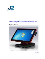
4.2.1 Size of the opening for cable routing in the 21.5" Copilot
Monitor positioned on the VESA arm.
The
Copilot 21.5'' Monitor
can be installed in the
recessed or wall mounted version, prepared to be con-
nected to a VESA100 arm.
-
Close the covers taking care to reposition the
insulating gaskets and screw O-rings (for models with
IP67 protection).
It is possible to adjust and tighten the VESA100 joint
of the
Copilot 21.5'' Monitor
(available as an option)
using a normal grinder key (cod. 90006195).
4.3 Panel mounting
-
Drilling the panel according to the dimensions
indicated: 320 x 528
4.3.1 Panel drilling jig
-
Remove the
Copilot 21.5" Monitor
from its
packaging and place it on a flat surface free of objects,
placing a soft cloth on the table itself to avoid scratch-
ing the glass during installation. Place the Copilot 21.5"
Monitor with the glass facing the table. Avoid even mo-
mentarily placing the terminal in a vertical position or
slightly leaning against the mechanism to avoid damage
due to the unstable position.
-
Remove the 6 M5 screws that secure the upper
and lower sides.
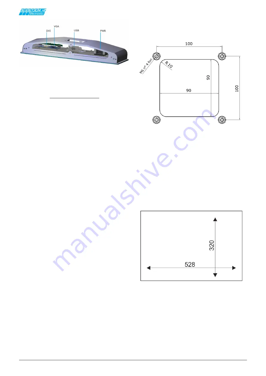
Figure 4.1.1: Bottom door connectors view.
***


