background image

3R-770.6-1 / 3R-770.46-1 


Instruction for Dynafix base for CMM 


12


System 3R International AB 

©  

I-814-E 02.12 Subject to modifications 


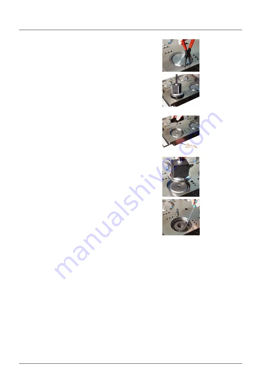
3.  Remove the retaining 

ring with pliers. 

Work with one piston 

at a time. 


4.  Remove the top cover 

with the aid of a 

magnet. Check O-

ring (H), replace if 

necessary. 


5.  Remove the screw in 

the middle. Hold 

piston from 

underneath with an 

allen key. 


6.  Remove disc with a 

magnet. Check O-

ring (I). Replace if 

necessary. 


7.  Take out the disc 

springs with a 

screwdriver, check 

each spring (G). 

Replace if necessary. 


Summary of Contents for 3R-770.46-1

Page 1: ...i814e DOC Instruction for Dynafix base for CMM 3R 770 6 1 3R 770 46 1 I 814 E 02 12...

Page 2: ...nd are well conversant with the contents Keep this instruction in a safe place for future reference This equipment may never be used by itself or in combination with other equipment or accessories for...

Page 3: ...ity affects the service interval The air should always be dried Oil mist lubrication is recommended Specification Dynafix Repetition Accuracy 0 002 mm Max Weight of workpiece 250 kg Clamping force 60...

Page 4: ...References Dimensions Accessory Master pallet F 3R 776 1 Master unit Junior 3R 406 11 Master unit Macro 3R 606 1 Control Unit 2x 3R 611 41 Dial indicator 3R 3 2 Air gun connector kit 3R SP20753 Palle...

Page 5: ...huck is designed for mounting on the machine table A control unit is used to maneuver the chuck with compressed air All air connections are on the same side of the chuck The marked connections provide...

Page 6: ...the air pressure on for maximum locking force with exception for Combi which however requires to have the air turned off Opening sequence unclamp The chuck is closed in the idle position and can only...

Page 7: ...lamp chamber with a finger or other aid by pressing the valve at connection Unclamp 1 for Dynafix and 11 for chuck in center The springloaded piston is activated and clamp the pallet in chuck 5 Air gu...

Page 8: ...eto 76HF or Corr 1142 before it is mounted on the machine table Mount the chuck onto the machine table 1 Align the chuck on machine table that either reference axis or surface is parallel to machine a...

Page 9: ...time for the chuck must be at least 2 seconds when air blast is used When a continuous Turbo pressure is used the Turbo pressure must be turned off before the chuck can be opened Alignment Angle Place...

Page 10: ...chuck Center of the chuck can be found by indicating on the reference hole Distance to the Z references The Z height of the chuck is found by indicating on the Z references Aligning the chuck in cente...

Page 11: ...Clean and protect with antirust oil Daily Inspect and clean the chuck s X Y och Z references Weekly Clean and lubricate all ground reference surfaces Yearly Remove chuck from machine table and clean s...

Page 12: ...with pliers Work with one piston at a time 4 Remove the top cover with the aid of a magnet Check O ring H replace if necessary 5 Remove the screw in the middle Hold piston from underneath with an alle...

Page 13: ...Incorrect mounting of springs may damage the chuck full clamping force will not be achieved 2 Remount the disc Tightening torque is 40 Nm Difficulties in mounting the disc can be due to incorrectly mo...

Page 14: ...stem 3R International AB I 814 E 02 12 Subject to modifications Parts list Description Article no Quantity Seal A 20829 00 1 Screw 12 9 B MC6S 12x35 4 Washer C 10138 00 4 Air nipple D 45800 S021 4 Spr...

Reviews: