098-00028-000 Revision F – May, 2012
TimeProvider 5000 User’s Guide 475
Appendix C Installing the GPS Antenna
Antenna Installation
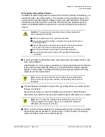
Developing a Grounding Scheme
In addition to determining where to locate and mount the antenna and cabling, you
should develop a grounding scheme. The purpose of the grounding scheme is to
provide some protection against voltage surges and static discharge. If transient
eliminators are used, they also need to be connected to the perimeter ground
system or bulkhead entrance panel that is connected to the perimeter ground
system.
In general, follow local building codes when selecting a grounding scheme, wire
size, and installation.
Use #6 AWG (13.3 mm) copper ground wire or larger, depending on the distance
to the earth ground electrode. Refer to your local electrical codes for specific
details. In most cases, 1/0 AWG (55.0 mm) ground wire will maintain 1/10 the
resistance of the coaxial shied..
Connect transient eliminators, if part of the grounding scheme, to earth ground
through a conductor.
Symmetricom makes no recommendation as to whether to install transient
eliminators. Symmetricom can provide suitable transient eliminators as an option.
Never connect antenna systems to the same earth ground connector as heating
and cooling systems, elevator or pump motors, or other motors or machinery
which can induce noise in the antenna system.
Caution:
To ensure proper grounding, observe these precautions
when installing the antenna:
Allow no sharp bends in the ground conductors.
Ensure that no painted surface insulates the transient eliminator or
grounding clamps.
Ensure that ground conductors are bonded to the metal enclosure
box (if used) and do not enter through an access hole.
Do not use soldered connections for grounding purposes.
Secure all grounding connections with mechanical clamp type
connectors.
Note:
Larger ground conductors provide better transient elimination;
that is, the larger the ground conductor, the less likely the chance of
transients.
Note:
Do not
connect the outside transient eliminator ground to the
inside equipment rack ground. Doing so can defeat the protection
afforded by the transient eliminator.
Summary of Contents for TimeProvider 5000
Page 12: ...Table of Contents 12 TimeProvider 5000 User s Guide 098 00028 000 Revision F May 2012 ...
Page 16: ...List of Figures 16 TimeProvider 5000 User s Guide 098 00028 000 Revision F May 2012 ...
Page 20: ...List of Tables 20 TimeProvider 5000 User s Guide 098 00028 000 Revision F May 2012 ...
Page 56: ...56 TimeProvider 5000 User s Guide 098 00028 000 Revision F May 2012 Chapter 1 Overview Alarms ...
Page 534: ...Index W W 534 TimeProvider 5000 User s Guide 098 00028 000 Revision F May 2012 ...

