1-5-3
L0700DC
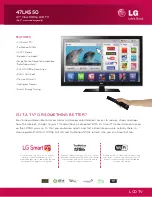
Reference Notes in the Table
1.
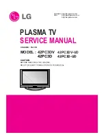
Caution:
Refer to “General Caution of Plasma Display” and “PDP Module Handling” of “IMPORTANT
SAFETY PRECAUTIONS” section not to injure and/or break the Plasma Display Module.
Fig. D1
Fig. D2
(S-1)
(S-1)
(S-1)
(S-1)
(S-1)
(S-1)
[1] Rear Cabinet
(S-6)
(S-5)
(S-5)
(S-7)
(S-3)
(S-3)
(S-2)
(S-4)
(S-4)
(S-4)
(S-4)
(S-2)
[6] Jack Holder
[7] Jack CBA
[5] Jack Bracket
[3] Fan
[2] Fan Holder
[4] PCB Box
Cover
(S-8)
Summary of Contents for 6842THG
Page 14: ...1 4 1 L0700IB BASIC SETUP AND OPERATING GUIDE...
Page 15: ...1 4 2 L0700IB...
Page 16: ...1 4 3 L0700IB...
Page 17: ...1 4 4 L0700IB...
Page 18: ...1 4 5 L0700IB...
Page 19: ...1 4 6 L0700IB...
Page 48: ...1 10 3 Analog 1 3 Schematic Diagram L0700SCA1...
Page 49: ...1 10 4 Analog 2 3 Schematic Diagram L0700SCA2...
Page 53: ...1 10 8 Power Supply 3 3 Schematic Diagram L0700SCP3...
Page 61: ...1 10 16 Digital 6 8 Schematic Diagram L0700SCD6...
Page 69: ...1 10 24 Jack CBA Top View Jack CBA Bottom View BL0700F01011 2...
Page 70: ...1 10 25 Switch CBA Top View Switch CBA Bottom View BL0700F01011 3...
Page 123: ...6842THG L0700UA 2006 05 25...