


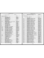


42MF439B/F7(A91H0UH)
R618
RES CARBON FILM T 1/4W J 330 OHM
RCX4331T1001
R619
RES CARBON FILM T 1/4W G 1.2K OHM
RCX4122T1002
R620
RES CARBON FILM T 1/4W G 10K OHM
RCX4103T1002
R621
RES CARBON FILM T 1/4W J 4.7K OHM
RCX4472T1001
R622
RES CARBON FILM T 1/4W G 2.7K OHM
RCX4272T1002
R624
RES CARBON FILM T 1/4W J 220 OHM
RCX4221T1001
R625
WIRE COPPER 6111-06003-0120
XZ40C0SHG002
R626
RES CARBON FILM T 1/4W J 1.2K OHM
RCX4122T1001
R627
RES CARBON FILM T 1/4W J 220 OHM
RCX4221T1001
R628
METAL OXIDE FILM RES. 2W J 0.27 OHM
RN02R27ZU001
R630
RES CARBON FILM T 1/4W J 22 OHM
RCX4220T1001
R631
METAL RESISTER. 2W J 0.56 OHM
RN02R56ZU001
R632
CHIP RES. 1/10W F 10K OHM
RRXAFR5H1002
R633
RES CARBON FILM T 1/4W J 68 OHM
RCX4680T1001
R634
RES CARBON FILM T 1/4W J 10 OHM
RCX4100T1001
R635
CHIP RES. 1/10W F 3.6K OHM
RRXAFR5H3601
R636
METAL RESISTER. 2W J 0.56 OHM
RN02R56ZU001
R638
WIRE COPPER 6111-06003-0120
XZ40C0SHG002
R639
WIRE COPPER 6111-06003-0120
XZ40C0SHG002
R640
RES. CARBON FILM J 1/2W J 820 OHM
RCX2821T1003
R641
RES CARBON FILM T 1/4W J 4.7K OHM
RCX4472T1001
R642
RES CARBON FILM T 1/4W J 220 OHM
RCX4221T1001
R643
RES CARBON FILM T 1/4W J 220 OHM
RCX4221T1001
R644
RES CHIP.(1608) 1/10W D 10K OHM
RRXADR5H1002
R645
RES CHIP.(1608) 1/10W D 10K OHM
RRXADR5H1002
R646
RES CHIP.(1608) 1/10W D 1.1K OHM
RRXADR5H1101
R647
RES CARBON FILM T 1/4W J 390 OHM
RCX4391T1001
R648
CHIP RES. 1/10W J 8.2K OHM
RRXAJR5Z0822
R649
RES CARBON FILM T 1/4W G 15K OHM
RCX4153T1002
R650
CHIP RES. 1/10W F 5.1K OHM
RRXAFR5H5101
R651
METAL OXIDE FILM RES 2W J 330 OHM
RN02331ZU001
R652
METAL OXIDE FILM RES 2W J 330 OHM
RN02331ZU001
R653
METAL OXIDE FILM RES 2W J 330 OHM
RN02331ZU001
R654
RES CARBON FILM T 1/4W J 560 OHM
RCX4561T1001
R655
CHIP RES. 1/10W J 10 OHM
RRXAJR5Z0100
R656
CHIP RES. 1/10W J 10 OHM
RRXAJR5Z0100
R657
METAL OXIDE FILM RES 2W J 330 OHM
RN02331ZU001
R658
CHIP RES. 1/10W F 270 OHM
RRXAFR5H2700
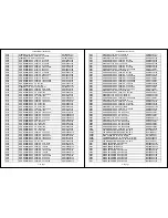
R701
CHIP RES. 1/10W J 10K OHM
RRXAJR5Z0103
R702
CHIP RES. 1/10W J 10K OHM
RRXAJR5Z0103
R704
CHIP RES. 1/10W J 220 OHM
RRXAJR5Z0221
R705
CHIP RES. 1/10W J 110 OHM
RRXAJR5Z0111
R706
CHIP CERAMIC CAP.(1608) CH J 100PF/50V
CHD1JJ3CH101
R707
CHIP RES.(1608) 1/10W 0 OHM
RRXAZR5Z0000
R709
CHIP RES.(1608) 1/10W 0 OHM
RRXAZR5Z0000
R710
CHIP RES. 1/10W J 75 OHM
RRXAJR5Z0750
R711
CHIP RES. 1/10W J 100 OHM
RRXAJR5Z0101
R712
CHIP RES. 1/10W J 75 OHM
RRXAJR5Z0750
R713
CHIP RES. 1/10W J 100 OHM
RRXAJR5Z0101
R714
CHIP RES. 1/10W J 33K OHM
RRXAJR5Z0333
R715
CHIP RES. 1/10W J 33K OHM
RRXAJR5Z0333
R717
CHIP RES. 1/10W J 33K OHM
RRXAJR5Z0333
R718
CHIP RES. 1/10W J 33K OHM
RRXAJR5Z0333
R720
CHIP RES. 1/10W J 75 OHM
RRXAJR5Z0750
R721
CHIP RES. 1/10W J 100 OHM
RRXAJR5Z0101
R723
CHIP RES. 1/10W J 75 OHM
RRXAJR5Z0750
R725
CHIP RES. 1/10W J 100 OHM
RRXAJR5Z0101
R726
CHIP RES. 1/10W J 75 OHM
RRXAJR5Z0750
R729
CHIP RES. 1/10W J 100 OHM
RRXAJR5Z0101
R730
CHIP RES. 1/10W J 33K OHM
RRXAJR5Z0333
7 / 15 page
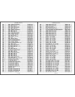
42MF439B/F7(A91H0UH)
R731
CHIP RES. 1/10W J 33K OHM
RRXAJR5Z0333
R732
CHIP RES. 1/10W J 33K OHM
RRXAJR5Z0333
R733
CHIP RES. 1/10W J 33K OHM
RRXAJR5Z0333
R740
CHIP RES. 1/10W J 33K OHM
RRXAJR5Z0333
R741
CHIP RES. 1/10W J 33K OHM
RRXAJR5Z0333
R743
CHIP RES. 1/10W J 33K OHM
RRXAJR5Z0333
R744
CHIP RES. 1/10W J 33K OHM
RRXAJR5Z0333
R752
CHIP RES. 1/10W J 75 OHM
RRXAJR5Z0750
R753
CHIP RES. 1/10W J 10 OHM
RRXAJR5Z0100
R754
CHIP RES. 1/10W J 75 OHM
RRXAJR5Z0750
R755
CHIP RES. 1/10W J 10 OHM
RRXAJR5Z0100
R756
CHIP RES. 1/10W J 75 OHM
RRXAJR5Z0750
R757
CHIP RES. 1/10W J 10 OHM
RRXAJR5Z0100
R759
CHIP RES. 1/10W J 33K OHM
RRXAJR5Z0333
R760
CHIP RES. 1/10W J 33K OHM
RRXAJR5Z0333
R762
CHIP RES. 1/10W J 33K OHM
RRXAJR5Z0333
R763
CHIP RES. 1/10W J 33K OHM
RRXAJR5Z0333
R764
CHIP RES. 1/10W J 560 OHM
RRXAJR5Z0561
R765
CHIP RES. 1/10W J 560 OHM
RRXAJR5Z0561
R766
CHIP RES. 1/10W J 100K OHM
RRXAJR5Z0104
R767
CHIP RES. 1/10W J 100K OHM
RRXAJR5Z0104
R768
CHIP RES.(1608) 1/10W 0 OHM
RRXAZR5Z0000
R769
CHIP RES.(1608) 1/10W 0 OHM
RRXAZR5Z0000
R770
RES CARBON FILM T 1/4W J 1.0K OHM
RCX4102T1001
R771
RES CARBON FILM T 1/4W J 1.0K OHM
RCX4102T1001
R772
CHIP RES. 1/10W J 75 OHM
RRXAJR5Z0750
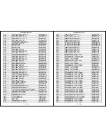
R801
CHIP RES. 1/10W J 10K OHM
RRXAJR5Z0103
R802
CHIP RES. 1/10W J 3.3K OHM
RRXAJR5Z0332
R804
WIRE COPPER 6111-06003-0120
XZ40C0SHG002
R805
CHIP RES. 1/10W F 27K OHM
RRXAFR5H2702
R806
CHIP RES. 1/10W F 11K OHM
RRXAFR5H1102
R807
CHIP RES. 1/10W F 11K OHM
RRXAFR5H1102
R809
CHIP RES. 1/10W J 4.7K OHM
RRXAJR5Z0472
R810
CHIP RES.(1608) 1/10W 0 OHM
RRXAZR5Z0000
R813
WIRE COPPER 6111-06003-0120
XZ40C0SHG002
R816
CHIP RES. 1/10W J 15K OHM
RRXAJR5Z0153
R817
CHIP RES. 1/10W J 5.6K OHM
RRXAJR5Z0562
R818
RES CARBON FILM T 1/4W J 2.2 OHM
RCX42R2T1001
R819
RES CARBON FILM T 1/4W J 2.2 OHM
RCX42R2T1001
R820
RES CARBON FILM T 1/4W J 2.2 OHM
RCX42R2T1001
R821
RES CARBON FILM T 1/4W J 2.2 OHM
RCX42R2T1001
R822
CHIP RES. 1/10W J 1K OHM
RRXAJR5Z0102
R823
CHIP RES. 1/10W J 22K OHM
RRXAJR5Z0223
R825
RES CARBON FILM T 1/4W J 39K OHM
RCX4393T1001
R826
RES CARBON FILM T 1/4W J 100K OHM
RCX4104T1001
R827
CHIP RES. 1/10W J 100K OHM
RRXAJR5Z0104
R828
CHIP RES. 1/10W J 20K OHM
RRXAJR5Z0203
R829
CHIP RES. 1/10W J 100 OHM
RRXAJR5Z0101
R830
RES CARBON FILM T 1/4W J 100K OHM
RCX4104T1001
R831
CHIP RES. 1/10W J 100K OHM
RRXAJR5Z0104
R833
CHIP RES. 1/10W J 39K OHM
RRXAJR5Z0393
R834
CHIP RES. 1/10W J 20K OHM
RRXAJR5Z0203
R837
CHIP RES. 1/10W J 100 OHM
RRXAJR5Z0101
R838
RES CARBON FILM T 1/4W J 22K OHM
RCX4223T1001
R839
CHIP RES. 1/10W J 22K OHM
RRXAJR5Z0223
R851
CHIP RES. 1/10W J 15K OHM
RRXAJR5Z0153
R852
CHIP RES. 1/10W J 5.6K OHM
RRXAJR5Z0562
R853
CHIP RES. 1/10W J 100K OHM
RRXAJR5Z0104
R854
CHIP RES. 1/10W J 10K OHM
RRXAJR5Z0103
R866
CHIP RES. 1/10W J 22K OHM
RRXAJR5Z0223
8 / 15 page
Summary of Contents for 42MF439B/F7
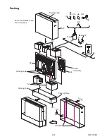
Page 14: ...4 2 A91H1DC 2 Rear Cabinet S 1 1 Stand Assembly S 2 S 3 S 2 S 2 S 2 S 4 S 5 Fig D1 ...
Page 40: ...10 4 A91H1SCJP2 Jack Power 2 3 Schematic Diagram ...
Page 41: ...10 5 A91H1SCJP3 Jack Power 3 3 Schematic Diagram ...
Page 45: ...10 9 A91H1SCIR IR Sensor Junction Schematic Diagram ...


