


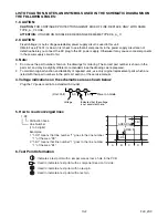


8-5
A91H1TR
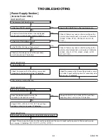
Replace Digital Main CBA Unit or LCD Module
Assembly.
Is 5V voltage supplied to the Pin(2, 29, 33, 39, 44) of IC401?
Is 8.2V voltage supplied to the Pin(12) of IC401?
Replace IC401.
Check P-ON+5V, P-ON+8.2V line
and service it if defective.
Yes
No
Yes
Yes
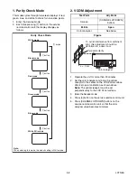
FLOW CHART NO.3
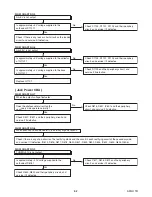
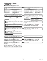
Picture does not appear normally. (EXT. input)
FLOW CHART NO.4
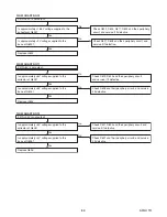
Picture does not appear normally. (Tuner input)
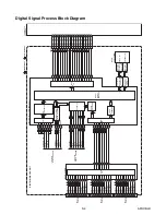
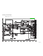
Are the video signals inputted to each pin of IC401?
Check the line between video input terminal and
each pin of IC401.
Are the video signals outputted to each pin of IC401?
Yes
No
No
No
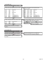
IC401
VIDEO-IN 1
3PIN
IC401
Y-IN 1
1PIN
IC401
CVBS/Y/S-Y-IN
38PIN
IC401
Pb-IN
36PIN
IC401
Pr/S-C-IN
34PIN
IC401
C-IN 1
9PIN
IC401
VIDEO-IN 2
7PIN
IC401
Y-IN 2
5PIN
IC401
C-IN 2
11PIN
IC401
COMPONENT-Y-IN
43PIN
IC401
COMPONENT-Pb-IN
47PIN
IC401
COMPONENT-Pr-IN
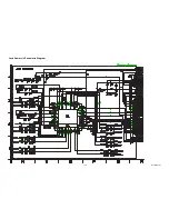
VIDEO-IN 1
Y-IN 1
C-IN 1
VIDEO-IN 2
Y-IN 2
C-IN 2
COMPONENT-Y-IN
COMPONENT-Pb-IN
COMPONENT-Pr-IN
52PIN
IC401
3PIN
IC401
1PIN
IC401
9PIN
IC401
7PIN
IC401
5PIN
IC401
11PIN
IC401
43PIN
IC401
47PIN
IC401
52PIN
→
JK703
→
JK702
→
JK702
→
JK707
→
JK706
→
JK706
→
JK717
→
JK718
→
JK719
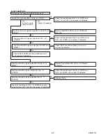
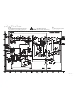
Check the line between Pin(3, 4) of CN201 and
Pin(12, 13) of TU101, and service it if defective.
Are the DIF signal inputted to Pin(3, 4) of CN201?
Replace Digital Main CBA Unit or LCD Module
Assembly.
Summary of Contents for 42MF439B/F7
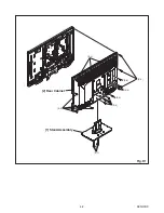
Page 14: ...4 2 A91H1DC 2 Rear Cabinet S 1 1 Stand Assembly S 2 S 3 S 2 S 2 S 2 S 4 S 5 Fig D1 ...
Page 40: ...10 4 A91H1SCJP2 Jack Power 2 3 Schematic Diagram ...
Page 41: ...10 5 A91H1SCJP3 Jack Power 3 3 Schematic Diagram ...
Page 45: ...10 9 A91H1SCIR IR Sensor Junction Schematic Diagram ...


