


5-3
LC7NEA
The white balance adjustment should be
performed when replacing the LCD Panel
or Digital CBA.
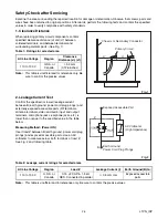
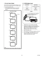
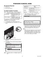
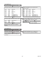
3. White Balance Adjustment
Purpose:
To mix red, green and blue beams correctly
for pure white.
Symptom of Misadjustment:
White becomes bluish
or reddish.
1. Operate the unit for more than 20 minutes.
2. Input the White Raster(70%=70IRE, 40%=40IRE).
3. Set the color analyzer to the CHROMA mode and
bring the optical receptor to the center on the
LCD-Panel surface after zero point calibration as
shown above.
Note:
The optical receptor must be set
perpendicularly to the LCD Panel surface.
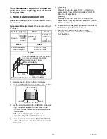
4. Enter the Service mode. Press [VOLUME DOWN]
button on the service remote control unit and select
“C/D” mode.
5.
[CUTOFF]
Press [1] button to select “COR” for Red Cutoff
adjustment. Press [3] button to select “COB” for
Blue Cutoff adjustment.
[DRIVE]
Press [4] button to select “DR” for Red Drive
adjustment. Press [6] button to select “DB” for Blue
Drive adjustment.
6. In each color mode, press [CHANNEL UP/DOWN]
buttons to adjust the values of color.
7. Adjust Cutoff and Drive so that the color
temperature becomes 12000°K (x= 0.272 / y=
0.278 ±0.005).
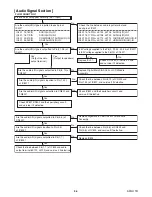
Test Point Adj. Point
Mode
Input
Screen
[VOLUME
DOWN]
button
[VIDEO1]
C/D
White Raster
(APL 70%)
or
(APL 40%)
M. EQ.
Spec.
Pattern Generator,
Color analyzer
x= 0.272 ± 0.005
y= 0.278 ± 0.005
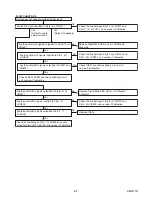
Figure
Color Analyzer
L = 3 cm
Perpendicularity
INPUT: WHITE 70%, 40%
To avoid interference from ambinent
light, this adjustment should be
performed in a dark room.
40%=40IRE
70%=70IRE
100IRE
100IRE
0IRE
0IRE
INPUT SIGNAL
Low
Light
Hight
Light
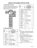
Summary of Contents for 42MF439B/F7
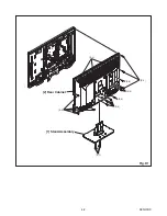
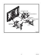
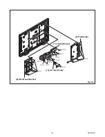
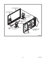
Page 14: ...4 2 A91H1DC 2 Rear Cabinet S 1 1 Stand Assembly S 2 S 3 S 2 S 2 S 2 S 4 S 5 Fig D1 ...
Page 40: ...10 4 A91H1SCJP2 Jack Power 2 3 Schematic Diagram ...
Page 41: ...10 5 A91H1SCJP3 Jack Power 3 3 Schematic Diagram ...
Page 45: ...10 9 A91H1SCIR IR Sensor Junction Schematic Diagram ...


