


4-1
A91H1DC
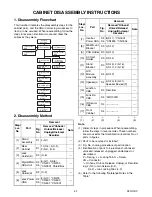
CABINET DISASSEMBLY INSTRUCTIONS
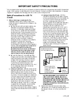
1. Disassembly Flowchart
This flowchart indicates the disassembly steps for the
cabinet parts, and the CBA in order to gain access to
item(s) to be serviced. When reassembling, follow the
steps in reverse order. Bend, route and dress the
cables as they were.
2. Disassembly Method
Note:
(1) Order of steps in procedure. When reassembling,
follow the steps in reverse order. These numbers
are also used as the Identification (location) No. of
parts in figures.
(2) Parts to be removed or installed.
(3) Fig. No. showing procedure of part location
(4) Identification of parts to be removed, unhooked,
unlocked, released, unplugged, unclamped, or
desoldered.
P = Spring, L = Locking Tab, S = Screw,
CN = Connector
* = Unhook, Unlock, Release, Unplug, or Desolder
e.g. 2(S-2) = two Screws (S-2),
2(L-2) = two Locking Tabs (L-2)
(5) Refer to the following "Reference Notes in the
Table."
Step/
Loc.
No.
Part
Removal
Fig.
No.
Remove/*Unhook/
Unlock/Release/
Unplug/Unclamp/
Desolder
Note
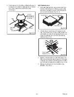
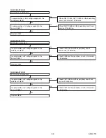
[1]
Stand
Assembly
D1 4(S-1)
---
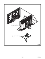
[2]
Rear
Cabinet
D1
11(S-2), 4(S-3),
2(S-4), (S-5)
---
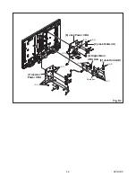
[3]
Jack
Holder(D)
D2 (S-6)
---
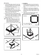
[4]
Digital Main
CBA Unit
D2
D5
6(S-7), 4(S-8),
*CN201, *CN202,
*CN3901, Shield Box
---
[5]
Jack
Holder(A)
D2 (S-9)
---
[6]
Jack Power
CBA
D2
D5
6(S-10), *CN203,
*CN801, *CN802,
*CN901, *CN1501
---
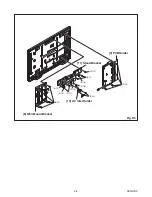
[1] Stand
Assembly
[2] Rear Cabinet
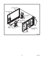
[13] Speaker(s)
[7] Inverter
Power CBA
[10] AC Inlet
Holder
[11] Stand
Bracket
[3] Jack Holder
(D)
[5] Jack Holder
(A)
[9] PCB Holder
[8] Wall Mount
Bracket
[4] Digital Main
CBA Unit
[6] Jack Power
CBA
[12] LCD Module
Assembly
[17] Front
Cabinet
[16] IR Sensor
CBA
[14] Junction
CBA
[15] Function
CBA
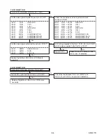
[7]
Inverter
Power CBA
D2
D5
8(S-11), *CN1601,
*CN1803, *CN1804
---
[8]
Wall Mount
Bracket
D3 4(S-12)
---
[9]
PCB Holder D3 4(S-13)
---
[10]
AC Inlet
Holder
D3 2(S-14)
---
[11]
Stand
Bracket
D3
2(S-15), 2(S-16),
4(S-17), 2(S-18)
---
[12]
LCD
Module
Assembly
D4 6(S-19)
---
[13] Speaker(s)
D4
4(S-20), 8(S-21),
Speaker Box(es)[F]
---
[14]
Junction
CBA
D4 Desolder
---
[15]
Function
CBA
D4 *WH1301B
---
[16]
IR Sensor
CBA
D4 ---------------
---
[17]
Front
Cabinet
D4 ---------------
---
↓
(1)
↓
(2)
↓
(3)
↓
(4)
↓
(5)
Step/
Loc.
No.
Part
Removal
Fig.
No.
Remove/*Unhook/
Unlock/Release/
Unplug/Unclamp/
Desolder
Note
Summary of Contents for 42MF439B/F7
Page 14: ...4 2 A91H1DC 2 Rear Cabinet S 1 1 Stand Assembly S 2 S 3 S 2 S 2 S 2 S 4 S 5 Fig D1 ...
Page 40: ...10 4 A91H1SCJP2 Jack Power 2 3 Schematic Diagram ...
Page 41: ...10 5 A91H1SCJP3 Jack Power 3 3 Schematic Diagram ...
Page 45: ...10 9 A91H1SCIR IR Sensor Junction Schematic Diagram ...


