


5-2
LC7NEA
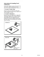
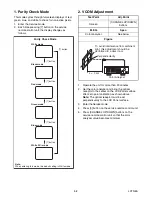
1. Purity Check Mode
This mode cycles through full-screen displays of red,
green, blue, and white to check for non-active pixels.
1. Enter the Service mode.
2. Each time pressing [7] button on the service
remote control unit, the display changes as
follows.
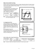
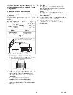
2. VCOM Adjustment
1. Operate the unit for more than 20 minutes.
2. Set the color analyzer and bring the optical
receptor to the center on the LCD-Panel surface
after zero point calibration as shown above.
Note:
The optical receptor must be set
perpendicularly to the LCD Panel surface.
3. Enter the Service mode.
4. Press [3] button on the service remote control unit.
5. Press [CHANNEL UP/DOWN] buttons on the
service remote control unit so that the color
analyzer value becomes minimum.
[7] button
Note:
When entering this mode, the default setting is White mode.
Purity Check Mode
[7] button
Red mode
Green mode
Blue mode
Black mode
[7] button
White mode
[7] button
[7] button
White 20% mode
[7] button
Test Point
Adj. Point
Screen
[CHANNEL UP/DOWN ]
buttons
M. EQ.
Spec.
Color analyzer
See below
Figure
Color Analyzer
To avoid interference from ambinent
light, this adjustment should be
performed in a dark room.
L = 3 cm
Perpendicularity
Summary of Contents for 42MF439B/F7
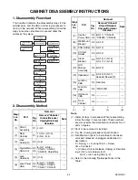
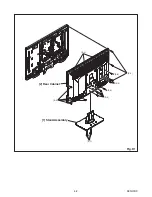
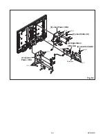
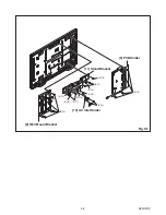
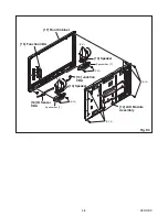
Page 14: ...4 2 A91H1DC 2 Rear Cabinet S 1 1 Stand Assembly S 2 S 3 S 2 S 2 S 2 S 4 S 5 Fig D1 ...
Page 40: ...10 4 A91H1SCJP2 Jack Power 2 3 Schematic Diagram ...
Page 41: ...10 5 A91H1SCJP3 Jack Power 3 3 Schematic Diagram ...
Page 45: ...10 9 A91H1SCIR IR Sensor Junction Schematic Diagram ...


