6
Combination of one 25060-1 and one 25060-2 Board.
( )
If you have one -1 board and one -2 board a combination of the above
instructions should be followed. First take the -2 unit and turn it so that
the edge connectors are nearest you. At the bottom left corner of the board
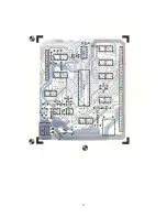
you will notice what looks like an IC made up of jumpers in a socket. Remove
the jumper block with a screwdriver and bend upward (straight out) the pins
that go to terminals DS2, DS3 and MX. Replace the jumper block in its socket.
Directly above the jumper block you will notice what appears to be a 14 pin
IC in a socket. This is not an IC but is an array of pull-up resistors. Slide
a screwdriver under this array and remove it. It should not be re-installed.
This drive is now programmed to be DRIVE 0.
( )
Now take the -1 drive and bend up pins DS1 and DS3. Re-install the jumper
block. You will notice in the middle of the board two small connector pads
marked MUX. This trace should be cut with a knife or razor blade.
( )
This drive is now programmed as DRIVE 1.
FINAL ASSEMBLY
( )
Some drives have the printed circuit board held in place with four metal
spring clips. If yours is of this type use two rubber bands for each drive to
help the retaining clips hold the board in place.
( )
Now
that both drives have been programmed you are ready to install them in
the chassis. DRIVE 0 should be installed first nearest the power supply. The
drive should be installed so that the jumper block is toward the TOP of the
chassis. Connect the power supply connector to J2 of the drive and mount the
drive from the bottom of the chassis using two 6-32 X 1/4 screws.
( )
Connect the other power supply connector to J2 of DRIVE 1 and install this
drive next to the first. Again orient the drive so that the jumper block is
toward the top. Use two 6-32 X 1/4 screws to secure the drive.
( )
Insert the
1 1/2 inch hole bushings in the rear of the chassis. Install the
bushings from the outside of the chassis.


