background image


10

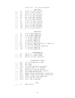
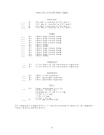
Parts List - DC-1 Disk Controller 

Resistors 

____  

R1 

4.7K 

 1/4 watt resistor 

____  

R2 

1M 

 1/4 watt resistor 

____  

R3 

750K 

 1/4 watt resistor 

____  

R4 

150 

 1/4 watt resistor 

____  

R5 

150 

 1/4 watt resistor 

____  

R6 

150 

 1/4 watt resistor 

____  

R7 

150 

 1/4 watt resistor 

____  

R8 

4.7K 

 1/4 watt resistor 

____  

R9 

4.7K 

 1/4 watt resistor 

____  

R10  680 

 1/4 watt resistor 

____  

R11  100 

 1/4 watt resistor 

____  

R12  4.7M 

 1/4 watt resistor 

____  

R13  1K 

 1/4 watt resistor 


Capacitors 

____   C1 

0.01 uF disc capacitor 

____   C2 

0.01 uF disc capacitor 

____   C3 

0.01 uF disc capacitor 

____   C4 

0.1 uF disc capacitor 

____   C5 

0.1 uF disc capacitor 

____   C6 

20 pF disc capacitor 

____   C7 

0.1 uF disc capacitor 

____  *C8 

100 uF @ 16 volt electrolytic capacitor 

____   C9 

0.1 uF disc capacitor 

____  *C10 

22 uF @ 6.3v tantalum capacitor 

____   C11 

0.1 uF disc capacitor 

____   C12 

0.1 uF disc capacitor 
 

Semiconductors 

____  *D1 

1N4733 5.1 v zener diode 

____  *D2 

1N4742 12 v zener diode 

____  *Ql 

SS 1122 silicon transistor 
 

Integrated Circuits 

____  *IC1 

1771 Disk controller (MOS) 

____ *IC2  555 

timer 

____ *IC3  555 

timer 

____  *IC4 

7407 open collector hex buffer 

____  *IC5 

74LS139  Dual 2 to 4 decoder 


*IC6 

DM8097/74367 hex bus driver 

____  *IC7 

7406 open collector hex inverter 

____  *IC8 

74175 Quad D flip-flop 

____  *IC9 

DM8835 Quad bi-directional transceiver 

____  *IC10  DM8835 Quad bi-directional transceiver 
____  *IC11  74LS00  Quad 2 input NAND gate 
____  *IC12  4049 (MOS) Hex inverter 
____  *IC13  7805 5 volt regulator 


Misc. 

____   Y1 

1MHz Crystal 


Summary of Contents for MF-68

Page 1: ...components from the bottom side of the board The plating provides the electrical connection from the BOTTOM to the TOP foil of each hole Unless otherwise noted it is important that none of the connections be soldered until all of the components of each group have been installed on the board This makes it much easier to interchange components if a mistake is made during assembly Be sure to use a lo...

Page 2: ...or should now be attached to the board Install the connector from the TOP side of the board and orient the connector such that the pins face the top edge of the board Solder The crystal should now be installed on the board Bend the crystal s leads at a 90 angle approx inch from its body and mount from the top side of the board After soldering fasten the crystal to the board using a short piece of ...

Page 3: ... match with that shown on the component layout drawing for each of the IC s Working from the TOP side of the circuit board fill in all of the feed thru s with molten solder The feed thru s are those unused holes on the board whose internal plating connects the TOP and BOTTOM circuit connections Filling these feed thru s with molten solder guarantees the integrity of the connections and increase th...

Page 4: ... block with a screw driver and bend upward straight out the pins that go to terminals DS2 DS3 T1 T2 T3 T4 and T5 Do not break off these pins Replace the jumper block in the socket This jumper will select this drive for DRIVE 0 the lowest number and most dominant give in the system As a double check the only position that should have a connected jumper is DS1 In the center of the board you will not...

Page 5: ...a screwdriver and bend upward straight the pins that go to terminals DS2 DS3 and MX not break these pins off Re install the jumper block into the socket As a double check the jumper block should have pins inserted only in terminals DS1 HS and the unlabeled pin There should be nothing plugged into the HM position Directly above this jumper block you will notice what appears to be a 14 pin IC in a s...

Page 6: ...the middle of the board two small connector pads marked MUX This trace should be cut with a knife or razor blade This drive is now programmed as DRIVE 1 FINAL ASSEMBLY Some drives have the printed circuit board held in place with four metal spring clips If yours is of this type use two rubber bands for each drive to help the retaining clips hold the board in place Now that both drives have been pr...

Page 7: ...SWTPC 6800 computer one minor modification needs to be made to the mother board Power down the computer and carefully remove the mother board With a short length of wire connect the two end pins of I 0 socket 5 This will connect the 5 chip select line to UD3 When connecting the wire route it around the PC support on the bottom of the board to prevent it from being cut Re install the mother board w...

Page 8: ...omputer should respond with SWTPC READY At this point you are in the disk operating system If the system does not boot up correctly reset the program counter to 0100 and again type G If after several tries the computer fails to respond with ready then the system is not operating properly If this is the case refer to the In Case of Problems section Using the Disk System The ME 68 Minifloppy Disk Sy...

Page 9: ...turn the diskette to its storage envelope whenever it is removed from a drive 2 Keep diskettes away from magnetic fields and from ferromagnetic materials which might become magnetized Strung magnetic fields can distort recorded data on the disk 3 Replace storage envelopes when they become worn cracked or distorted Envelopes are designed to protect the disk 4 Do not write on the plastic jacket with...

Page 10: ...0 pF disc capacitor ____ C7 0 1 uF disc capacitor ____ C8 100 uF 16 volt electrolytic capacitor ____ C9 0 1 uF disc capacitor ____ C10 22 uF 6 3v tantalum capacitor ____ C11 0 1 uF disc capacitor ____ C12 0 1 uF disc capacitor Semiconductors ____ D1 1N4733 5 1 v zener diode ____ D2 1N4742 12 v zener diode ____ Ql SS 1122 silicon transistor Integrated Circuits ____ IC1 1771 Disk controller MOS ____...

Page 11: ...11 ...

Page 12: ...end the leads parallel to the board on the foil side and trim so that 1 16 to 1 8 of wire remains Solder Attach all of the diodes to the circuit board Be sure the banded end of each diode matches with the outline shown in the component layout drawing Using some 18 gauge buss wire install jumpers in the two locations indicated with the number 12 Solder Make sure NO jumper is installed in the 24 pos...

Page 13: ...o chassis assembly Snap the four nylon printed circuit board mounts onto the chassis in the positions corresponding to the mounting holes on the circuit board Attach the clamps for electrolytic capacitors C3 and C4 to the chassis using 6 32 X 1 4 screws lockwashers and nuts Orient the clamps as shown in the chassis pictorial Leave the mounting screws loose until the capacitors have been installed ...

Page 14: ...st be tightened evenly and with enough pressure to slightly compress the transistor insulators The entire bottom of the transistor case must be in solid contact with the insulator for good heat transfer Orient the printed circuit board as shown in the chassis pictorial and snap it onto its mounts For American standard 120 VAC line operation complete steps 13 thru 16 of the wiring table For Europea...

Page 15: ...listed below If you find that any of the voltages do not measure as specified immediately remove power and recheck all wiring and solder connections Connectors JO and J1 Pin Voltage Tolerance 1 12 VDC 5 2 0 VDC 5 3 0 VDC 5 4 5 VDC 5 If everything checks out as called for then remove power unplug the unit and go back to the main disk assembly instructions for final assembly and checkout Once you ar...

Page 16: ...rrent diode ____ D8 1N5402 high current diode ____ D9 1N5402 high current diode ____ D10 1N5402 high current diode ____ D11 1N4003 diode Capacitors ____ C3 20 000 mfd 25 VDC electrolytic capacitor ____ C4 29 000 mfd 15 VDC electrolytic capacitor Regulators ____ Q3 LM323 5 VDC regulator ____ Q4 LM317 adjustable regulator ____ Q5 LM317 adjustable regulator Misc ____ T1 Power transformer 50 60 Hz Pri...

Page 17: ...C OPERATION 13 5 T1 Black LS 1 A no 14 5 T1 White LS 1 A no 15 5 T1 Blk Wht F1 A no 16 5 T1 Blk Red Fl A yes 240 VAC OPERATION 17 5 T1 Black LS 1 A no 18 5 T1 White LS 1 C no 19 5 T1 Blk Red LS 1 C yes 20 5 T1 Blk Wht F1 A yes 21 line cord A LS 1 A yes 22 line cord B S1 A yes 23 10 18 S1 B yes F1 B yes 24 4 18 C3 lug yes C4 lug yes 25 9 18 C4 lug yes Q3 A4 yes 26 10 18 C4 lug yes Q3 A1 yes 27 11 1...

Page 18: ...ou cannot solve the kit may be returned for factory service Please return the entire kit Chassis case PC boards cable drives etc Be sure to include the supplied diskette containing FDOS Remove the power transformer This reduces postal costs and damage Selected individual boards may be returned but in most cases it is best to send the entire unit Do not remove the boards from the drives themselves ...

Page 19: ... will not service a kit if there is any postal damage until the claim is settled Include all relevant correspondence and a brief description of the difficulty Ship prepaid by UPS or insured Parcel Post We cannot pick up repairs sent by bus Ship to Southwest Technical Products Corp Repair Department Digital Group 219 W Rhapsody San Antonio Texas 78216 ...

Page 20: ...20 ...

Page 21: ...21 ...

Reviews: