3
NOTE: MOS integrated circuits are susceptible to damage by static
electricity. Although some degree of protection is provided internally within the
integrated circuits, their cost demands the utmost in care. Before opening and/or
installing any MOS integrated circuits, you should ground your body and all
metallic tools coming into contact with the leads thru a 1 M
Ω
1/4 watt resistor
(supplied with the kit). The ground must be an "earth" ground such as a water pipe,
and not the circuit board ground. As for the connection to your body, attach a clip
lead to your watch or metal ID bracelet. Make absolutely sure you have the 1 Meg
Ω
resistor connected between you and the "earth" ground, otherwise you will be
creating a dangerous shock hazard. Avoid touching the leads of the integrated
circuits any more than necessary when installing them, even if you are grounded.
The tip of the soldering iron should be grounded as well (separately from your body
ground) either with or without a 1 Meg al resistor. Most soldering irons having a
three prong line cord plug already have a grounded tip. Static electricity should
be an important consideration in cold, dry environments. It is less of a problem
when it is warm and humid.
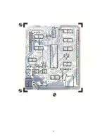
( ) Install MOS integrated circuits ICI and IC12 following the precautions given
in the preceding section. As each is installed, make sure it is down firmly
against the board before soldering all of its leads. Do not bend the leads on
the back side of the board. Doing so makes it very difficult to remove the
integrated circuits should replacement ever be necessary. The "dot" or
"notch" on the end of the package is used for orientation purposes and must
match with that shown on the component layout drawing for each of the IC's .
( )
Working from the "TOP" side of the circuit board, fill in all of the
feed-thru's with molten solder. The feed-thru's are those unused holes on the
board whose internal plating connects the "TOP" and "BOTTOM" circuit
connections. Filling these feed-thru's with molten solder guarantees the
integrity of the connections and increase the current handling capability.
( )
Now that all of the components have been installed on the board, double check
to make sure all have been installed correctly in their proper location.
( )
Check very carefully to make sure that all connections have been soldered. It
is very easy to miss some connections when soldering which can really cause
some hard to find problems later during checkout. Also look for solder
"bridges" and "cold" solder joints which are another common problem.
Since the circuit board now contains MOS devices, it is susceptible damage
from severe static electrical sources. One should avoid handling the board any more
than necessary and when you must, avoid touching or allowing anything to come into
contact with any of the conductors on the board.
( )
Now that the controller has been finished, assemble the power supply using
the P-200 MF instruction set.
( )
Now that the power supply has been assembled you are ready to program and
install the drives. The mini-floppy drives come pre-assembled and tested and
require no circuit modifications to work in an MF-68 System. The drives do
need to be programmed, however, to allow multiplexing of the drive select
signals to selectively enable multiple drives. Carefully remove both drives
from their boxes and turn the drives so that the edge connectors are nearest
you and so that the belt and pulleys are on the bottom. Immediately above J2
on the bottom right hand edge of the board you will notice the wording


