4
MINI
MINI
25060-1 or
25060-2
The number -1 or -2 denotes the circuit board revision number follow the
correct instructions below for the drives you have.
25060 -1 boards ( Both drives must be -1 )
( )
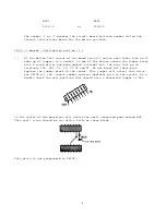
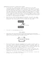
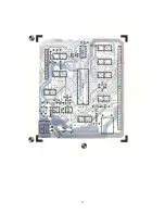
At the bottom left corner of the board you will notice what looks like an IC
made up of jumpers in a socket. On one of the drives remove the jumper block
with a screw driver and bend upward (straight out) the pins that go to
terminals DS2, DS3, T1, T2, T3 T4 and T5. Do not break off these pins.
Replace the jumper block in the socket. This jumper will select this drive
for DRIVE #0, the -lowest number and most dominant give in the system. As a
double check the only position that should have a connected jumper is DS1.
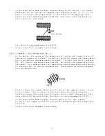
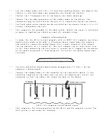
In the center of the board you will notice two small connected pads marked MUX.
This small trace should be cut with a knife or razor blade.
This drive is now programmed as DRIVE 0


