1
Assembly Instructions MF-68 Disk System
The MF-68 Disc System is a dual mini-floppy disc system designed for a SWTPC
6800 Computer System.
The MF-68 consists of three major parts: the controller, the chassis and
power supply and the drives themselves. The drives come pre-assembled and require
only minor jumper changes to be used. The power supply is assembled partially on a
small printed circuit board and partially thru point to point chassis wiring. The
controller is assembled entirely on a 5 3/4" x 5" circuit board that will plug into
an I/0 slot on the computer’s mother board. Connection between the controller and
the drives is made via a 34 conductor ribbon cable.
When assembling the unit, work first on the controller board, then the power
supply and finally the drive programming and chassis assembly.
When the MF-68 disc system is being assembled, work on only one part or board
at a time. The MOS integrated circuits supplied with this kit are susceptible to
static electricity damage and for this reason have reason have been packed with
their leads impressed onto a special conductive foam or possibly wrapped in a
conductive foil. In either case, do not remove the protective material until told
to do so later in the instructions.
Controller PC Board Assembly
NOTE: Since all of the holes on the PC board have been plated thru, it is
only necessary to solder the components from the bottom side of the board. The
plating provides the electrical connection from the "BOTTOM" to the "TOP" foil of
each hole. Unless otherwise noted, it is important that none of the connections be
soldered until all of the components of each group have been installed on the
board. This makes it much easier to interchange components if a mistake is made
during assembly. Be sure to use a low wattage iron (not a gun) with a small tip. Do
not use acid core solder or any type of paste flux. We will not guarantee or repair
any kit on which either product has been used. Use only the solder supplied with
the kit or a 60/40 alloy resin core equivalent. Remember all of the connections are
soldered on the bottom side of the board only. The plated-thru holes provide the
electrical connection to the top foil.
( )
Before installing any parts on the circuit board, check both sides of the
board over carefully for incomplete etching and foil "bridges" or "breaks".
It is unlikely that you will find any, but should there be, especially on the
"TOP" side of the board, it will be very hard to locate and correct after all
of the components have been installed on the board.
( )
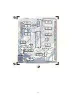
Attach all of the resistors to the board. As with all other components unless
noted, use the parts list and component layout drawing to locate each part
and install from the "TOP" side of the board bending the leads along the
"BOTTOM" side of the board and trimming so that 1/16" to 1/8" of wire
remains. Solder.
Scanned and edited by Michael Holley Feb 17, 2004
Southwest Technical Products Corporation Document Circa 1977


