


1-12-1
D6N_SC
SCHEMATIC DIAGRAMS / CBA’S AND TEST POINTS
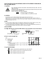
Standard Notes
WARNING
Many electrical and mechanical parts in this chassis
have special characteristics. These characteristics
often pass unnoticed and the protection afforded by
them cannot necessarily be obtained by using
replacement components rated for higher voltage,
wattage, etc. Replacement parts that have these
special safety characteristics are identified in this
manual and its supplements; electrical components
having such features are identified by the mark “
#
” in
the schematic diagram and the parts list. Before
replacing any of these components, read the parts list
in this manual carefully. The use of substitute
replacement parts that do not have the same safety
characteristics as specified in the parts list may create
shock, fire, or other hazards.
Notes:
1. Do not use the part number shown on these
drawings for ordering. The correct part number is
shown in the parts list, and may be slightly
different or amended since these drawings were
prepared.
2. All resistance values are indicated in ohms
(K = 10
3
, M = 10
6
).
3. Resistor wattages are 1/4W or 1/6W unless
otherwise specified.
4. All capacitance values are indicated in
µ
F
(P = 10
-6
µ
F).
5. All voltages are DC voltages unless otherwise
specified.
Summary of Contents for CWV20V6
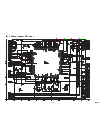
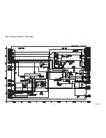
Page 37: ...1 12 3 Main 1 7 Schematic Diagram VCR Section E9AB1SCM1...
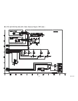
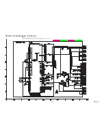
Page 38: ...1 12 4 Main 2 7 Power SW DVD Open Close SW Sensor Schematic Diagram VCR Section E9AB1SCM2...
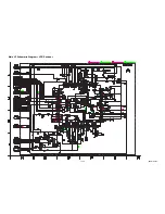
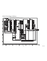
Page 39: ...1 12 5 Main 3 7 Schematic Diagram VCR Section E9AB1SCM3...
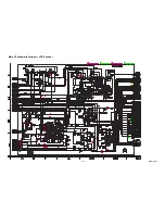
Page 40: ...1 12 6 Main 4 7 Schematic Diagram VCR Section E9AB1SCM4...
Page 41: ...1 12 7 Main 5 7 Schematic Diagram VCR Section E9AB1SCM5...
Page 42: ...1 12 8 Main 6 7 Schematic Diagram VCR Section E9AB1SCM6...
Page 43: ...1 12 9 Main 7 7 Schematic Diagram VCR Section E9AB1SCM7...
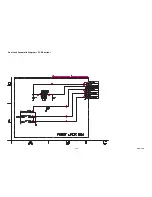
Page 45: ...1 12 11 Front Jack Schematic Diagram VCR Section E9AB1SCJK...
Page 82: ...CWV20V6 E9AB1CD 2006 10 6...


