


1-9-1
E9AB0FW
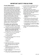
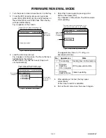
FIRMWARE RENEWAL MODE
1. Turn the power on and remove the disc on the tray.
2. To put the DVD recorder into version up mode,
press [DVD], [CM SKIP], [6], [5], and [4] buttons on
the remote control unit in the order. Then the tray
will open automatically.
Fig. a appears on the screen.
3. Load the disc for version up.
Fig. c appears on the screen. The file on the top is
highlighted as the default.
When there is only one file to exist, Step 4 will
start automatically.
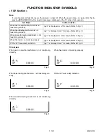
4. Select the firmware version pressing arrow
buttons, then press [OK].
Fig. d appears on the screen. The DVD recorder
starts updating.
The appearance shown in (*1) of Fig. d is
described as follows.
5. After updating is finished, the tray opens
automatically.
At this time, no button is available.
6. Pull out the AC code once, then insert it again.
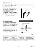
Fig. a Version Up Mode Screen
* Firmware Version differs depending on the
models, and this indication is one example.
Current
F/W version
is displayed.
Firm Update Mode
Please insert a disc.
ver. R3F10210S1E
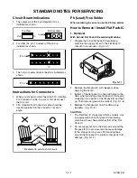
Fig. c Update Disc Screen
* Firmware Version differs depending on the
models, and this indication is one example.
Disc name
is displayed.
Firm Update Mode
ver. R3F10210S1E
VOL_200512250934
1 R3F10210S1E
2 R3F10211S1E
3 R3F10212S1E
4 R3F10213S1E
1 / 1
Files included
in the disc are
displayed.
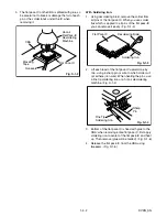
No.
Appearance
State
1
File Loading...
Sending files into the memory
2
Firmware
Updating...
XX% Complete.
Writing new version data
---
Firmware
Update Failure
Failed in updating
Fig. d Programming Mode Screen
* Firmware Version differs depending on the
models, and this indication is one example.
Selected
F/W version
is displayed.
Firm Update Mode
ver.
R3F10210S1E
R3F10210S1E
File Loading...
(*1)
Summary of Contents for CWV20V6
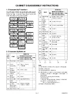
Page 37: ...1 12 3 Main 1 7 Schematic Diagram VCR Section E9AB1SCM1...
Page 38: ...1 12 4 Main 2 7 Power SW DVD Open Close SW Sensor Schematic Diagram VCR Section E9AB1SCM2...
Page 39: ...1 12 5 Main 3 7 Schematic Diagram VCR Section E9AB1SCM3...
Page 40: ...1 12 6 Main 4 7 Schematic Diagram VCR Section E9AB1SCM4...
Page 41: ...1 12 7 Main 5 7 Schematic Diagram VCR Section E9AB1SCM5...
Page 42: ...1 12 8 Main 6 7 Schematic Diagram VCR Section E9AB1SCM6...
Page 43: ...1 12 9 Main 7 7 Schematic Diagram VCR Section E9AB1SCM7...
Page 45: ...1 12 11 Front Jack Schematic Diagram VCR Section E9AB1SCJK...
Page 82: ...CWV20V6 E9AB1CD 2006 10 6...


