


1-6-1
E9AB1DC
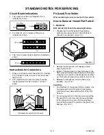
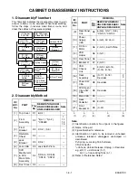
CABINET DISASSEMBLY INSTRUCTIONS
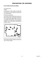
1. Disassembly Flowchart
This flowchart indicates the disassembly steps to gain
access to item(s) to be serviced. When reassembling,
follow the steps in reverse order. Bend, route, and
dress the cables as they were originally.
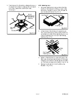
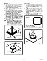
2. Disassembly Method
Note:
(1): Identification (location) No. of parts in the figures
(2): Name of the part
(3): Figure Number for reference
(4): Identification of parts to be removed, unhooked,
unlocked, released, unplugged, unclamped, or
desoldered.
P=Spring, L=Locking Tab, S=Screw,
CN=Connector
*=Unhook, Unlock, Release, Unplug, or Desolder
e.g. 6(S-1) = six Screws (S-1),
5(L-1) = five Locking Tabs (L-1)
(5): Refer to “Reference Notes.”
ID/
LOC.
No.
PART
REMOVAL
Fig.
No.
REMOVE/*UNHOOK/
UNLOCK/RELEASE/
UNPLUG/DESOLDER
Note
[1]
Top Cover
D1
6(S-1)
---
[2]
Front
Assembly
D2
*5(L-1), *3(L-2),
*CN1609
1
1-1
1-2
1-3
[3]
Front
Bracket
D2
2(S-2), (S-3)
---
[4]
Radiation
Sheet
D2
----------
---
[5]
Jack
Bracket
D3
2(S-4)
---
[6]
Jack CBA
D3
Jack Earth Plate
---
[7]
DVD
Mechanism
& DVD
Main CBA
Assembly
D4
2(S-5A), 2(S-5B),
*CN101, *CN701
---
[8]
Dust Cover
D4
----------
---
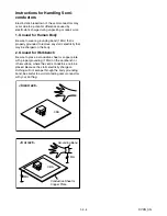
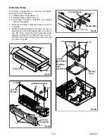
[1] Top Cover
[2] Front
Assembly
[4] Radiation
Sheet
[3] Front
Bracket
[5] Jack
Bracket
[6] Jack CBA
[7] DVD
Mechanism
& DVD Main
CBA Assembly
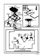
[9] Rear
Panel Unit
[10] Power
Supply CBA
[11] DC
Fan Motor
[12] PCB
Holder
[13] Rear
Panel
[14] Bracket R
[16] Deck
Assembly
[20] Deck
Pedestal
[18] DVD Open
/Close SW CBA
[15] VCR
Chassis Unit
[17] Power
SW CBA
[19] Main
CBA
[21] Front
Bracket R
[8] Dust Cover
[9]
Rear Panel
Unit
D5
6(S-6), 3(S-7), (S-8),
*CN101, *CN102
---
[10]
Power
Supply
CBA
D6
4(S-9), AC Cord
---
[11]
DC Fan
Motor
D6
2(S-10), Earth Plate
---
[12]
PCB
Holder
D6
3(S-11)
---
[13]
Rear Panel
D6
----------
---
[14]
Bracket R
D7
2(S-12)
---
[15]
VCR
Chassis
Unit
D7
5(S-13), 6(S-14),
(S-15), (S-16)
---
[16]
Deck
Assembly
D8
(S-17), (S-18),
Desolder
2
3
[17]
Power SW
CBA
D8
Desolder
---
[18]
DVD Open/
Close SW
CBA
D8
Desolder
---
[19]
Main CBA
D8
----------
---
[20]
Deck
Pedestal
D9
8(S-19)
---
[21]
Front
Bracket R
D9
(S-20)
---
↓
(1)
↓
(2)
↓
(3)
↓
(4)
↓
(5)
ID/
LOC.
No.
PART
REMOVAL
Fig.
No.
REMOVE/*UNHOOK/
UNLOCK/RELEASE/
UNPLUG/DESOLDER
Note
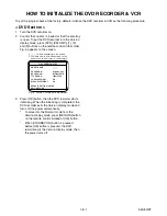
Summary of Contents for CWV20V6
Page 37: ...1 12 3 Main 1 7 Schematic Diagram VCR Section E9AB1SCM1...
Page 38: ...1 12 4 Main 2 7 Power SW DVD Open Close SW Sensor Schematic Diagram VCR Section E9AB1SCM2...
Page 39: ...1 12 5 Main 3 7 Schematic Diagram VCR Section E9AB1SCM3...
Page 40: ...1 12 6 Main 4 7 Schematic Diagram VCR Section E9AB1SCM4...
Page 41: ...1 12 7 Main 5 7 Schematic Diagram VCR Section E9AB1SCM5...
Page 42: ...1 12 8 Main 6 7 Schematic Diagram VCR Section E9AB1SCM6...
Page 43: ...1 12 9 Main 7 7 Schematic Diagram VCR Section E9AB1SCM7...
Page 45: ...1 12 11 Front Jack Schematic Diagram VCR Section E9AB1SCJK...
Page 82: ...CWV20V6 E9AB1CD 2006 10 6...