background image

10-12

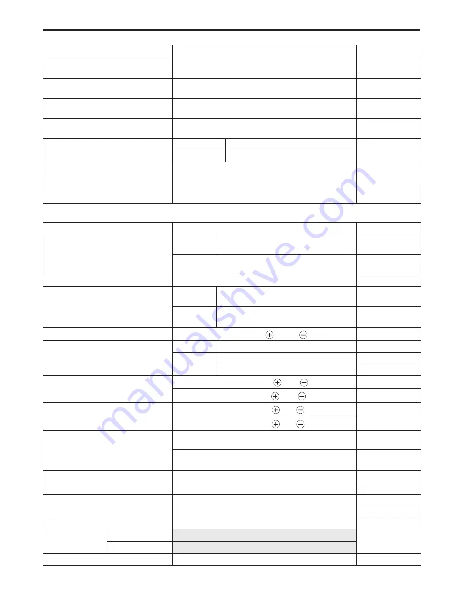
DR-Z400/EK1 (’01-MODEL)

ITEM

STANDARD/SPECIFICATION

LIMIT

Rear shock absorber gas

900 kPa

pressure

(9.0 kgf/cm

2

, 128 psi)

———

Rear shock absorber oil type

SUZUKI REAR SUSPENSION OIL SS-25

or an equivalent suspension oil

———

Rear shock absorber oil capacity

380 ml

(12.8/13.4 US/Imp oz)

———

Rear shock absorber spring

258.0

pre-set length

(10.2)

———

Rear shock absorber damping

Rebound

13th clicks turn back

———

force adjuster

Compression

12th clicks turn back

———

Rear wheel travel

295

(11.6)

———

Swingarm pivot shaft runout

0.3

———

(0.01)

ELECTRICAL

ITEM

SPECIFICATION

NOTE

Spark plug

Type

DENSO: U24ESR-N

NGK: CR8E

Gap

0.7 – 0.8 mm

(0.028 – 0.031 mm)

Spark performance

Over 8 mm (0.3 in) at 1 atm.

Ignition coil resistance

Primary

0.1 – 1.0 

Terminal –

Ground

Secondary

12 – 20 k

Plug cap –

Terminal

Ignition coil primary peak voltage

More than 150 V ( 

 : B/W, 

 : B/Y)

Generator coil resistance

Charging

0.50 – 1.25 

Y – Y

Signal coil

0.05 – 0.20 

B – W

Pick-up coil

390 – 600 

G – Bl

Pick-up coil peak voltage

More than 10.0 V ( 

 : Bl, 

 : G)

DR-Z400

More than 5.0 V ( 

 : Bl, 

 : G)

DR-Z400E

Signal coil peak voltage

More than 1.0 V ( 

 : B, 

 : W)

DR-Z400

More than 1.4 V ( 

 : B, 

 : W)

DR-Z400E

Generator no-load voltage

More than 55 V (AC) at 5 000 r/min.

(when engine is cold)

(Y – Y)

DR-Z400

More than 75 V (AC) at 5 000 r/min.

(Y – Y)

DR-Z400E

Regulated voltage

12.5 – 14.0 V at 5 000 r/min.

DR-Z400

13.5 – 15.0 V at 5 000 r/min.

DR-Z400E

Generator Max. output

150 W at 5 000 r/min.

DR-Z400

200 W at 5 000 r/min.

DR-Z400E

Starter relay resistance

3 – 5 

DR-Z400E

Battery

Type designation

* YT7B-BS

DR-Z400E

Capacity

* 12 V 21.6 kC (6 Ah)/10 HR

Fuse size

10 A

DR-Z400E

Summary of Contents for drz 400E

Page 1: ...DR Z400 E 9 9 5 0 0 4 3 0 2 2 0 1 E...

Page 2: ...al motorcycle Illustrations in this manual are used to show the basic principles of operation and work pro cedures They may not represent the actual mo torcycle exactly in detail This manual is writte...

Page 3: ...ec tion to help you find the item and page you need COMPONENT PARTS AND WORK TO BE DONE Under the name of each system or unit there is an exploded view which provides work instructions and other servi...

Page 4: ...0 25010 For the other countries Apply SUZUKI SILICONE GREASE 99000 25100 Apply SUZUKI MOLY PASTE 99000 25140 Apply SUZUKI BOND 1207B 99104 31140 For USA 99000 31140 For the other countries Apply SUZUK...

Page 5: ...R Z400Y DR Z400EY 2000 MODEL 1 4 SERIAL NUMBER LOCATION 1 4 FUEL OIL AND ENGINE COOLANT RECOMMENDATIONS 1 4 FUEL 1 4 ENGINE OIL 1 5 BRAKE FLUID 1 5 FRONT FORK OIL 1 5 REAR SHOCK ABSORBER OIL 1 5 ENGIN...

Page 6: ...good judgement and basic mechanical safety principles If you are unsure about how to perform a particular service operation ask a more experienced mechanic for advice GENERAL PRECAUTIONS Proper servi...

Page 7: ...d bolts tighten the larger sizes first Always tighten the nuts and bolts from the inside working out diagonally and to the specified torque Whenever you remove oil seals gaskets packing O rings self l...

Page 8: ...FUEL FOR THE OTHER COUNTRIES Gasoline used should be graded 95 octane Research Method or higher Unleaded gasoline is recom mended Difference between photographs and the actual motorcycle depends on th...

Page 9: ...not reuse brake fluid left over from the last servicing or which has been stored for a long period of time FRONT FORK OIL Use SUZUKI FORK OIL SS 05 or an equivalent fork oil REAR SHOCK ABSORBER OIL Us...

Page 10: ...moving parts to BREAK IN before subjecting the engine to maximum stresses The future performance and reliability of the engine depends on the care and restraint exercised during its early life Refer...

Page 11: ...or PLATE NAME APPLIED SPECIFICATION E 01 E 03 E 28 1 Engine starting label DR Z400E 2 Noise label 3 ICES Canada label 4 Manual notice label 5 Warning safety label 6 Frame serial number plate 7 Compli...

Page 12: ...rs 1 Bore 90 0 mm 3 543 in Stroke 62 6 mm 2 465 in Piston displacement 398 cm3 24 3 cu in Compression ratio 12 2 1 Carburetor KEIHIN FCR39 Air cleaner Polyurethane foam element Starter system Primary...

Page 13: ...brake Rear brake Disc brake Front tire size 80 100 21 51M Rear tire size 110 100 18 64M ELECTRICAL Ignition type Electronic ignition CDI Ignition timing 7 BTDC at 1 800 r min Spark plug NGK CR8E DENS...

Page 14: ...1 10 GENERAL INFORMATION COUNTRY AND AREA CODES The following are codes and their applicable country or area CODE COUNTRY OR AREA E 01 General E 03 USA E 28 Canada...

Page 15: ...RESSION LEVER DR Z400 2 10 ENGINE OIL AND OIL FILTER 2 11 ENGINE OIL HOSES 2 12 THROTTLE CABLE PLAY 2 13 ENGINE IDLE SPEED 2 14 ENGINE COOLANT 2 14 RADIATOR HOSES 2 15 CLUTCH 2 16 DRIVE CHAIN 2 16 BRA...

Page 16: ...nut and bolts T T T Tappet clearance I I Spark plug I R Spark arrester C C Fuel line I I I Replace every four years Decompression lever DR Z400 I I I Engine oil and oil filter R R Engine oil hoses I I...

Page 17: ...a proper size with a nonflammable cleaning solvent Immerse the air cleaner element in the cleaning sol vent and wash it Press the air cleaner element between the palms of both hands to remove the exc...

Page 18: ...ve the right frame cover 6 2 Tighten the exhaust pipe nut 1 exhaust pipe bolt 2 muffler connection bolt 3 muffler mounting bolt 4 and muffler mount ing nut 5 to the specified torque Exhaust pipe nut a...

Page 19: ...ton must be at top dead center TDC on the compres sion stroke in order to check or adjust the tappet clearance The tappet clearance should only be checked when the en gine is cold Remove the generator...

Page 20: ...for details NOTE Be sure to apply molybdenum oil solution to the top and bot tom faces of the tappet shim When installing the tappet shim make sure that the side with the numbers face towards the tap...

Page 21: ...70 2 75 2 80 2 85 2 90 2 95 3 00 3 05 3 10 3 15 3 20 3 25 3 30 3 35 3 40 3 45 3 50 3 50 2 55 2 60 2 75 2 80 2 85 2 90 2 95 3 00 3 05 3 10 3 15 3 20 3 25 3 30 3 35 3 40 3 45 3 50 3 50 2 60 2 65 2 80 2...

Page 22: ...0 2 95 3 00 3 05 3 10 3 15 3 20 3 25 3 30 3 35 3 40 3 45 3 50 3 50 2 55 2 60 2 75 2 85 2 95 2 80 2 85 2 90 2 95 3 00 3 05 3 10 3 15 3 20 3 25 3 30 3 35 3 40 3 45 3 50 3 50 2 60 2 65 2 80 2 90 2 30 2 3...

Page 23: ...p Spark plug gap Standard 0 7 0 8 mm 0 028 0 031 in 09900 20803 Thickness gauge ELECTRODE Check the condition of the electrode If the electrode is extremely worn or burnt replace the spark plug with a...

Page 24: ...tarting difficulties or engine damage Check the lever clearance and if necessary adjust as follows Adjust the tappet clearance 2 5 to 2 8 Loosen the locknuts 1 Turn the adjuster 2 to provide the speci...

Page 25: ...qt of oil Use an engine oil that meets API service classifications SF or SG and that has a viscosity rating of SAE 10W 40 Engine oil drain plug on the crankcase 1 21 N m 2 1 kgf m 15 0 lb ft on the f...

Page 26: ...lled improperly serious engine damage may result ENGINE OIL HOSES Inspect initially at five hours of operation and every 30 hours thereafter Inspect the engine oil hoses for damage and oil leakage If...

Page 27: ...ration If the adjustment is necessary adjust the thread length in the following way Loosen the locknut 3 Turn the nut 4 to obtain the thread length A of 3 mm 0 12 in Tighten the locknut 3 securely PUL...

Page 28: ...an overflow tank at the end of the breather hose Therefore the engine coolant level may decrease while riding Check the engine coolant level before every ride Remove the radiator cap 1 and check that...

Page 29: ...R BLEEDING THE ENGINE COOLANT CIRCUIT Bleed air from the air bleeder bolt 3 Tighten the air bleeder bolt 3 to the specified torque Air bleeder bolt 6 0 N m 0 6 kgf m 4 3 lb ft Add engine coolant up to...

Page 30: ...using a jack or wooden block and turn the rear wheel slowly by hand Visually inspect the drive chain for the possible damages listed below Loose pins Twisted or seized links Damaged rollers Kinked or...

Page 31: ...and rear wheels are correctly aligned Drive chain slack 40 50 mm 1 6 2 0 in After adjusting the drive chain tighten the rear axle nut 3 to the specified torque Rear axle nut 100 N m 10 0 kgf m 72 5 lb...

Page 32: ...When the wear exceeds the grooved limit line replace the pads with new ones 6 46 and 6 55 Replace the brake pads as a set otherwise braking per formance will be adversely affected BRAKE PEDAL HEIGHT...

Page 33: ...luid make sure to seal the con tainer completely and keep it out of the reach of chil dren When replenishing brake fluid make sure not to get any dust or other foreign materials in the fluid Brake flu...

Page 34: ...valve Repeat this process until the fluid flowing into the receptacle no longer contains air bubbles NOTE While bleeding the brake system replenish the brake fluid in the reservoir as necessary Make...

Page 35: ...ones TIRES Check tire pressure and the tire for damage each time the motorcycle is ridden TIRE TREAD CONDITION Operating the motorcycle with excessively worn tires will de crease riding stability and...

Page 36: ...FLATION TIRE PRESSURE kPa kgf cm2 psi FRONT 100 1 0 14 REAR 100 1 0 14 The standard tire fitted on this motorcycle is a 80 100 21 51M for the front and a 110 100 18 64M for the rear The use of tires o...

Page 37: ...d With the wheel facing straight ahead grasp the lower fork tubes near the axle and pull forward If play is found adjust the steering 6 23 FRONT FORK Inspect initially at five hours of operation and e...

Page 38: ...g pin 18 1 8 13 0 B Brake hose union bolt front rear 23 2 3 16 5 C Brake air bleeder valve front rear 7 5 0 75 5 5 D Brake disc mounting bolt front rear 10 1 0 7 0 E Swingarm pivot nut 77 7 7 55 5 F R...

Page 39: ...PERIODIC MAINTENANCE 2 25 D 0 2 U 1 3 A B C 7 6 4 5 8 9 B D L U K C B E P T R M F N P J H I G O G Q T S...

Page 40: ...t and wipe off any grease oil dirt or grime Lubricate exposed parts which are subject to rust with a rust preventative spray especially whenever the motorcycle has been operated under wet or rainy con...

Page 41: ...fective cylinder head gasket NOTE When the compression pressure goes below specification check the engine for conditions listed above COMPRESSION TEST PROCEDURE NOTE Before testing the engine for comp...

Page 42: ...O ring Defective oil pump Combination of the above items HIGH OIL PRESSURE Engine oil viscosity is too high Clogged oil passage Combination of the above items OIL PRESSURE TEST PROCEDURE Connect a ta...

Page 43: ...TCH 3 37 GEARSHIFT FORK AND GEAR 3 38 TRANSMISSION 3 39 BEARINGS 3 42 OIL SEALS 3 45 ENGINE REASSEMBLY 3 47 CRANKSHAFT 3 47 GEARSHIFT CAM AND FORK 3 48 CRANKCASE 3 49 STARTER CLUTCH AND GENERATOR ROTO...

Page 44: ...Kick lever DR Z400 3 4 3 10 Clutch pressure plate drive plates and driven plates 3 16 3 56 Clutch sleeve hub 3 16 3 56 Primary driven gear assembly 3 17 3 56 Oil pump drive driven gear 3 18 3 53 Oil p...

Page 45: ...gine removal is sequentially explained in the following steps Remove the seat and frame covers 6 2 Drain the engine oil 2 11 Drain the engine coolant 2 15 Remove the carburetor 4 10 Disconnect the bat...

Page 46: ...ngine coolant overflow tank mounting bolt Disconnect the spark plug cap 1 engine oil breather hose 2 engine oil hose 3 and engine oil tank 4 Remove the clutch release arm 5 Remove the starter motor 6...

Page 47: ...NGINE 3 5 Remove the exhaust pipe 1 and muffler 2 Disconnect the radiator hoses Disconnect the decompression cable DR Z400 Disconnect the engine oil pipe 3 and engine oil hose union bolt 4 1 2 1 3 3 4...

Page 48: ...n the washer 1 and remove the engine sprocket nut 2 while pressing down on the rear brake pedal Remove the cotter pins and brake pedal Replace the removed cotter pins with new ones Remove the engine s...

Page 49: ...ENGINE 3 7 Remove the engine from the frame...

Page 50: ...ce the nut has been removed it is no longer of any use Replace the engine mounting nuts with new ones Hold the bolthead with a wrench and then tighten the en gine mounting nuts to the specified torque...

Page 51: ...pin Tighten the engine sprocket nut to the specified torque Engine sprocket nut 110 N m 11 0 kgf m 79 5 lb ft NOTE When tightening the engine sprocket nut depress the brake pedal Bend the washer secur...

Page 52: ...R 1303 Pour 1 9 L 2 0 US qt 1 7 Imp qt of an API service classified SF or SG engine oil that has a viscosity rating of SAE 10W 40 into the oil filler hole located in the frame after overhauling it Sta...

Page 53: ...urn the generator rotor until the T line on the generator rotor is aligned with the center of the hole in the generator cover NOTE When removing the cylinder head cover the piston must be at TDC of th...

Page 54: ...ot drop the dowel pins into the crankcase Remove the cylinder head side bolt NOTE Do not drop the cam chain into the crankcase Remove the four cylinder head bolts in diagonal stages NOTE Before loosen...

Page 55: ...ng a plas tic mallet Remove the cylinder gasket 5 and dowel pins 6 Place a clean rag over the cylinder base to prevent the pis ton pin circlip from dropping into the crankcase Remove the piston pin ci...

Page 56: ...r DR Z400E Remove the starter driven gear 3 dowel pins 4 and gasket 5 Remove the oil filter cap 6 and oil filter 7 Remove the starter drive gear cover 1 and starter drive gear 2 DR Z400E Remove the ge...

Page 57: ...ht crankcase cover Remove the dowel pins 1 and gasket 2 Loosen the clutch spring set bolts working in diagonal stages and then remove them when they are fully loosened Remove the water pump cover Remo...

Page 58: ...using the special tool and then remove the clutch sleeve hub nut 09920 53740 Clutch sleeve hub holder Remove the clutch sleeve hub and washer Remove the clutch pressure plate clutch drive plates and c...

Page 59: ...the primary driven gear assembly and collar Remove the cam chain tensioner 1 and cam chain 2 Remove the retainer 3 spacer 4 and kick starter driven gear 5 DR Z400 Remove the kick starter assembly 6 DR...

Page 60: ...d oil pump assembly Do not remove the circrip A before separating the crankase to prevent the oil pump idle gear shaft from dropping into the crankcase Remove the gearshift shaft 4 by removing the cir...

Page 61: ...gear bolt Hold the generator rotor using the special tool DR Z400 or a 26 mm offset wrench DR Z400E and then remove the balancer driven gear nut 09930 44913 Rotor holder Remove the washer balancer dri...

Page 62: ...kcase securing bolts Remove the right crankcase securing bolts Separate the crankcase using the special tool 09920 13120 Crankcase separating tool NOTE Fit the crankcase separating tool to the right s...

Page 63: ...e the countershaft assembly 1 and driveshaft assem bly 2 Remove the balancer shaft Remove the crankshaft from the crankcase using the spe cial tool 09920 13120 Crankcase separating tool Remove the oil...

Page 64: ...r original posi tions Remove the intake pipe Remove the engine coolant hose housing Remove the tappets 1 and shims 2 by hand or by using a magnet Compress the valve springs and then remove the valve c...

Page 65: ...stortion us ing a straightedge and thickness gauge Take clearance read ings at several places If any clearance reading exceeds the ser vice limit replace the cylinder head with a new one 09900 20803 T...

Page 66: ...VALVE STEM DEFLECTION Lift the valve about 10 mm 0 39 in from the valve seat Mea sure the valve stem deflection in two directions X and Y per pendicular to each other Position the dial gauge as shown...

Page 67: ...e reamer 10 8 mm 09916 34542 Reamer handle Oil the stem hole of each valve guide and drive the guide into the guide hole using the valve guide installer and attach ment 09916 44310 Valve guide remover...

Page 68: ...1 mm 0 035 0 043 in If the valve seat is out of specification re cut the seat VALVE SEAT SERVICING The valve seats for both the intake and exhaust valves are ma chined to three different angles The se...

Page 69: ...CUT Descale and clean up the seat using the 45 cutter Rotate the cutter one or two turns Measure the valve seat width W after every cut If the valve seat is pitted or burned use the 45 cutter to condi...

Page 70: ...t to the correct width After the desired seat position and width is achieved use the 60 cutter very lightly to clean up any burrs caused by the previous cutting operations DO NOT use a lapping compoun...

Page 71: ...results in reduced engine power output and accounts for the chattering noise coming from the valve mechanism Check the valve springs for proper strength by measuring their free length and also by the...

Page 72: ...Install the valve spring with the smaller pitch A facing the cylinder head B Larger pitch C Down Install the valve spring retainer by pressing down the spring using the valve lifter Fit the cotter hal...

Page 73: ...d power output Measure the cam height H using the micrometer If the cams are worn to the service limit replace the camshaft with new a one 09900 20202 Micrometer 25 50 mm Cam height H Service Limit IN...

Page 74: ...lastigauge If the camshaft journal oil clearance exceeds the service limit measure the inside diameter of the camshaft journal holder and outside diameter of the camshaft journal Replace the camshaft...

Page 75: ...e Limit 0 05 mm 0 002 in CYLINDER BORE Inspect the cylinder wall for any scratches nicks or other dam age Measure the cylinder bore diameter at six places 09900 20508 Cylinder gauge set Cylinder bore...

Page 76: ...in Oil 2 01 2 03 mm 0 0791 0 0799 in Piston ring thickness Standard 1st 0 71 0 76 mm 0 0280 0 0299 in 1 08 1 10 mm 0 0425 0 0433 in 2nd 0 77 0 79 mm 0 0303 0 0311 in PISTON RING FREE END GAP AND PIST...

Page 77: ...ce the conrod with a new one 09900 20605 Dial calipers Conrod small end I D Service Limit 20 040 mm 0 7890 in CONROD DEFLECTION AND BIG END SIDE CLEARANCE Wear on the big end of the conrod can be esti...

Page 78: ...e 1 100 mm 09900 20701 Magnetic stand 09910 21304 V block set 100 mm Crankshaft runout Service Limit 0 08 mm 0 003 in STARTER CLUTCH DR Z400E Hold the rotor with a 26 mm offset wrench and remove the h...

Page 79: ...aw width No 1 No 2 Service Limit 13 2 mm 0 520 in STARTER TORQUE LIMITER DR Z400E Do not attempt to disassemble the starter torque lim iter It is unserviceable Check the slip torque of the starter tor...

Page 80: ...ness Standard 4 6 4 7 mm 0 181 0 185 in GEARSHIFT FORK AND GEAR GEARSHIFT FORK TO GEARSHIFT FORK GROOVE CLEARANCE Clearance for each gearshift fork plays an important role in the smoothness and positi...

Page 81: ...gear 3 Circlip 4 3rd drive gear 5 Circlip 6 4th drive gear 7 2nd drive gear 8 Circlip 9 Bearing 0 Bearing A Driveshaft B Washer C 2nd driven gear D Spacer E Bearing F Oil seal G 4th driven gear H 3rd...

Page 82: ...t expand the end gap larger than required to slip the circlip over the shaft After installing a new circlip make sure that it is completely seated in its groove and securely fit ted NOTE When reassemb...

Page 83: ...ENGINE 3 41 1 Countershaft 2 Driveshaft 2 1 A...

Page 84: ...earing remover set Replace the removed bearing with a new one Install the right countershaft bearings using the special tool 09913 70210 Bearing installer set Apply a small quantity of THREAD LOCK 134...

Page 85: ...et CRANKSHAFT BEARINGS Remove the bearing retainer Remove the right and left crankshaft bearings using the spe cial tools 09921 20220 Bearing remover set Replace the removed bearings with new ones Ins...

Page 86: ...ial tool 09913 70210 Bearing installer set LEFT GEARSHIFT CAM BEARING Remove the left gear shift cam bearing Replace the removed bearing with a new one Install the left gearshift cam bearing RIGHT BAL...

Page 87: ...se and generator rotor cover Pay attention to the following points Replace the removed oil seals with new ones Apply SUZUKI SUPER GREASE A to the lip of the oil seals For USA 99000 25030 SUZUKI SUPER...

Page 88: ...121 Oil seal remover Replace the removed oil seal with a new one Install the gearshift shaft oil seal into the left crankcase slowly using the special tool 09913 70210 Bearing installer set OIL CHECK...

Page 89: ...crankshaft Crank web to web width Standard 62 0 0 1 mm 2 441 0 004 in When mounting the crankshaft in the crankcase it is neces sary to pull its left end into the crankcase by using the special tools...

Page 90: ...gearshift fork shafts NOTE After the gearshift fork shaft and gearshift forks have been fitted make sure that the gears engage normally Set the transmission gears to the neutral position 1 Gearshift...

Page 91: ...stalling the sump filter wash the sump filter with clean ing solvent and then blow compressed air through it to dry it off Install the dowel pins to the left crankcase Apply engine oil to the conrod b...

Page 92: ...felt to rotation try to free the shafts by tapping them with a plastic mallet STARTER CLUTCH AND GENERATOR ROTOR Remove the grease from the tapered portion of the crank shaft and the generator rotor...

Page 93: ...n gear by aligning the matching marks Hold the generator rotor using the special tool DR Z400 or a 26 mm offset wrench DR Z400E and then tighten the balancer shaft nut to the specified torque 09930 44...

Page 94: ...old the generator rotor using the special tool DR Z400 or a 26 mm offset wrench DR Z400E and then tighten the primary drive gear nut to the specified torque 09930 44913 Rotor holder Primary drive gear...

Page 95: ...tity of THREAD LOCK 1342 or THREAD LOCK SUPER 1322 to the threaded parts of the oil pump mounting screws and then tighten them For USA 99000 32050 THREAD LOCK 1342 For the other countries 99000 32110...

Page 96: ...e kick starter with the line 3 on the kick starter shaft Install the kick starter shaft assembly and hook the end of the spring onto the crankcase boss 1 2 1 Oil seal 2 Guide 3 Spring 4 Kick starter s...

Page 97: ...m 1 0 kgf m 7 0 lb ft CLUTCH 1 2 1 Clutch release camshaft 2 Bolt 3 Spring retainer 4 Spring 5 Pressure plate 6 Drive plate 7 pcs 7 Driven plate 7 pcs 8 Drive plate 1 pc 9 Bearing 0 Push piece A Washe...

Page 98: ...washer 2 onto the clutch sleeve hub correctly Insert the clutch drive plates and driven plates one by one into the clutch sleeve hub in the prescribed order NOTE Be sure to install the drive plate wit...

Page 99: ...w gasket onto the right crankcase cover bolt A as shown CLUTCH COVER Tighten the clutch cover bolts securely NOTE Install the new gasket onto the clutch cover bolt A as shown GENERATOR ROTOR COVER Ins...

Page 100: ...crews securely PISTON RING Install the oil ring first the 2nd ring second and the 1st ring last NOTE The 1st 1 and 2nd 2 piston rings differ in shape The 1st and 2nd piston rings should be installed w...

Page 101: ...y molybdenum oil solution to the small end of the conrod Place a clean rag over the cylinder base to prevent the piston pin circlip from dropping into the crankcase and then fit the piston pin circlip...

Page 102: ...e cast in the crankcase Make sure that the guide 1 is inserted properly or binding of the cam chain and guide may result CYLINDER HEAD Install the dowel pins 1 and new gasket 2 Use a new cylinder head...

Page 103: ...33 5 lb ft NOTE Apply engine oil to the threaded parts of the cylinder head bolts and its washers Be sure to install the washer with rounded side facing up After tightening the cylinder head bolts to...

Page 104: ...t out 15 roller pins from the exhaust camshaft side going towards the intake camshaft side Engage the 15th roller pin on the cam chain with the arrow marked 3 3 on the intake sprocket Refer to the fol...

Page 105: ...osition must be at TDC on the compression stroke CYLINDER HEAD COVER Thoroughly wipe off oil from the fitting surfaces of the cylin der head and cover Apply SUZUKI BOND 1207B to the end caps of the cy...

Page 106: ...he chain tension adjuster body Use a new gasket to prevent oil leakage Install the cam chain tension adjuster body to the cylinder and then tighten the two Allen bolts to the specified torque Cam chai...

Page 107: ...3 REMOUNTING 4 3 CARBURETOR 4 4 CONSTRUCTION 4 4 SPECIFICATIONS 4 5 I D NO LOCATION 4 5 SLOW SYSTEM 4 6 COASTING ENRICHMENT SYSTEM 4 6 MAIN SYSTEM 4 7 ACCELERATOR PUMP SYSTEM 4 8 STARTER SYSTEM 4 9 F...

Page 108: ...t and side covers 6 2 Turn the fuel valve to the OFF position Disconnect the fuel hose Gasoline is highly flammable and explosive Keep heat sparks and flames away from gasoline Remove the fuel tank RE...

Page 109: ...ne Replace the removed O ring with a new one to pre vent fuel leakage Tighten the fuel valve mounting bolts to the specified torque Fuel valve mounting bolt 4 4 N m 0 44 kgf m 3 2 lb ft FUEL STRAINER...

Page 110: ...6 Intake joint 7 O ring 8 Slow air jet 9 Main air jet 0 Air jet A Throttle position sensor B Starter plunger C Hose D Coasting richer pump assembly E Hose F Hose G Pilot screw H Starter jet I Needle j...

Page 111: ...pe KEIHIN FCR39H Bore size 39 mm 1 5 in I D No 29F0 29F1 29F3 29F4 Idle r min 1800 100 r min Float height 9 0 1 0mm 0 35 0 04in Main jet M J 165 142 165 142 Main air jet M A J 200 Jet needle J N OBDXP...

Page 112: ...the pilot screw 5 and sprayed into the main bore through the pilot outlet 7 COASTING ENRICHMENT SYSTEM The coasting enrichment system is included in the slow system At normal operation joining of the...

Page 113: ...mixes with the air admitted through the main air jet 5 and then forms an emulsion The emulsified fuel then passes through the clearance between the needle jet 4 and jet needle 6 and is discharged into...

Page 114: ...correct the air fuel mixture ratio When the rider opens the throttle grip quickly the intake air volume increases and air velocity at the bottom of the piston valve is slow and sucking volume of fuel...

Page 115: ...ovide the proper air fuel mixture for starting This occurs when the mixture is sprayed out through the starter outlet port 6 into the main bore FLOAT SYSTEM The float 1 and needle valve 2 work in conj...

Page 116: ...Remove the left frame cover 6 2 Disconnect the throttle position sensor coupler Disconnect the throttle cables Disconnect the coasting richer pump hose Loosen the carburetor clamp screws and then remo...

Page 117: ...O ring with a new one to prevent fuel leakage Remove the coasting richer pump assembly Replace the removed O ring with a new one to prevent fuel leakage Remove the starter plunger Remove the top cap F...

Page 118: ...ly Remove the throttle valve Remove the float chamber Replace the removed O ring with a new one to prevent fuel leakage Remove the float pin 1 float 2 and needle valve 3 Remove the intake joint Replac...

Page 119: ...be handled carefully Always follow the chemical manufacturer s instructions for proper use handling and storage Clean all jets with a spray type carburetor cleaner and dry them using compressed air C...

Page 120: ...rmissible limits similar trouble will occur Conversely if the needle valve sticks the gasoline will not flow into the float chamber Clean the float chamber and float parts with gasoline If the needle...

Page 121: ...esistance 1 Approximately 5 k Measure the resistance 2 between the throttle position sen sor terminals as shown in the illustration Fully open the throttle valve with the throttle lever Position the t...

Page 122: ...N CONROD SMALL END CONROD BIG END BEARING OIL HOSE OIL HOSE RIGHT CRANKCASE LEFT CRANKCASE LEFT CRANKCASE OIL SUMP FILTER COUNTERSHAFT DRIVE GEARS PRIMARY GEARS CLUTCH PLATES KICK IDEL GEAR DR Z400 CO...

Page 123: ...COOLING SYSTEM 5 1 COOLING SYSTEM 5 CONTENTS COOLING SYSTEM 5 2 DESCRIPTION 5 2 CONSTRUCTION 5 3 ENGINE COOLANT 5 4 RADIATOR 5 5 INSPECTION 5 5 REMOVAL 5 6 REMOUNTING 5 6...

Page 124: ...nder and cylinder head and through the radiator A high capacity centrifugal pump is used for the water pump and a tube and fin type aluminum radiator which is characterized by lightness in weight and...

Page 125: ...tor inlet hose 5 Radiator outlet hose 6 Overflow hose 7 Overflow tank A Air bleeder bolt 1 Circlip 2 Water pump driven gear 3 Pin 4 Washer 5 Circlip 6 Bearing 7 O ring 8 Oil seal 9 Mechanical seal 0 I...

Page 126: ...l based antifreeze or different brands of antifreeze The percentage of antifreeze in the coolant should be between 50 to 60 If the percentage of antifreeze is above or below this range the coolant s f...

Page 127: ...tester put a rag on the filler to prevent the engine coolant from spray ing out Do not exceed the radiator cap release pressure or the radiator cap and subsequently the radiator can be damaged Check...

Page 128: ...ant may be harmful if swallowed or if it comes in contact with the skin or eyes If engine cool ant gets into the eyes or contacts the skin flush the eyes or wash the skin thoroughly with plenty of wa...

Page 129: ...ful if swallowed or if it comes in contact with the skin or eyes If engine cool ant gets into the eyes or contacts the skin flush the eyes or wash the skin thoroughly with plenty of wa ter If engine c...

Page 130: ...nstall the wedge from the opposite side and lock it into the slit of the bearing remover attachment Drive out the water pump bearing by knocking the wedge bar 09941 50111 Bearing remover Replace the r...

Page 131: ...O rings For USA 99000 25030 SUZUKI SUPER GREASE A For the other countries 99000 25010 SUZUKI SUPER GREASE A When installing the water pump driven gear align the pin 1 with the groove 2 After installi...

Page 132: ...ASSEMBLY AND REMOUNTING 6 38 REAR SHOCK ABSORBER DAMPING FORCE ADJUSTMENT 6 39 REAR SWINGARM AND CUSHION LEVER REMOVAL 6 40 INSPECTION AND DISASSEMBLY 6 41 REASSEMBLY AND REMOUNTING 6 43 FINAL INSPECT...

Page 133: ...ERS Remove the left and right side covers 1 FRAME COVERS Remove the left frame cover 1 and right frame cover 2 BATTERY COVER Remove the battery cover 1 REMOUNTING Remount the seat side covers frame co...

Page 134: ...ONSTRUCTION 1 Front axle 2 Odometer gearbox 3 Bearing R 4 Front wheel 5 Spacer 6 Bearing L 7 Dust seal 8 Brake disc 9 Spacer 0 Washer A Front axle nut B Brake disc mounting bolt ITEM N m kgf m lb ft A...

Page 135: ...6 4 CHASSIS Left Right Left Right Left Right Spacer Clearance...

Page 136: ...ut 1 and loosen the front axle pinch bolts 2 Support the motorcycle with a jack or wooden block and re move the front axle 3 and front wheel 4 Do not operate the brake lever during or after front whee...

Page 137: ...found replace the wheel hub dust seal with a new one Remove the wheel hub dust seal using the special tool 09913 50121 Oil seal remover Replace the removed dust seal with a new one WHEEL BEARINGS Insp...

Page 138: ...not ex ceed the service limit when checked as shown An excessive amount of runout is usually due to worn or loose wheel bearings and can be corrected by replacing the bearings If bearing re placement...

Page 139: ...set First install the left wheel bearing and then install the right wheel bearing 6 4 WHEEL HUB DUST SEAL Apply SUZUKI SUPER GREASE A to the lip of dust seal For USA 99000 25030 SUZUKI SUPER GREASE A...

Page 140: ...m 14 5 lb ft by holding the front axle using the special tools 09940 34520 T handle 09940 34581 Attachment F Tighten the front axle pinch bolts 4 to the specified torque Front axle pinch bolt 18 N m...

Page 141: ...ng B Oil seal C Oil seal retainer D Inner tube antifriction metal E Inner tube F Outer tube antifriction metal G Clamp H Boot I Clamp J Oil lock piece K Holder L Outer tube M O ring N End plate O O ri...

Page 142: ...the front fork upper clamp bolts 3 and lower clamp bolts 4 NOTE Slightly loosen the front fork cap bolt 5 to facilitate later disas sembly Remove the boot Replace the removed boot clamps with new one...

Page 143: ...E Hold the fork inverted for a few minutes to drain the oil Remove the push rod 1 needle 2 and return spring 3 Remove the dust seal 4 and stopper ring 5 Place the front fork in a vise with soft jaws N...

Page 144: ...n metal 5 and oil lock piece 6 The outer and inner tube s antifriction metals must be replaced along with the oil seal and dust seal when assembling the front fork INSPECTION FORK SPRING Measure the f...

Page 145: ...removal and disassembly Pay special attention to the following points ANTIFRICTION METALS OIL SEAL AND DUST SEAL Hold the inner tube vertically clean the metal groove and install the inner tube slide...

Page 146: ...rod bolt 80 N m 8 0 kgf m 58 0 lb ft Use a new O ring to prevent oil leakage FORK OIL Place the front fork vertically without the spring Pour the specified fork oil into the inner tube 99000 99001 SS5...

Page 147: ...al tool between the locknut and washer Slowly turn the cap bolt by hand until it is seated on the lock nut Tighten the locknut to the specified torque while holding the cap bolt 09940 94922 Front fork...

Page 148: ...upper clamp bolt 30 N m 3 0 kgf m 21 5 lb ft Front fork cap bolt 23 N m 2 3 kgf m 16 5 lb ft FRONT WHEEL 6 5 NOTE Before tightening the front axle nut and front axle pinch bolts move the front fork up...

Page 149: ...p 4 Steering stem head bracket 5 Steering stem nut 6 Bearing 7 Steering stem 8 Bearing A Handlebar clamp bolt B Steering stem head nut C Front fork upper clamp bolt D Front fork lower clamp bolt ITEM...

Page 150: ...Remove the front brake hose guide bolts Remove the odometer assembly Remove the clamps 1 and engine stop switch 2 Disconnect the main switch coupler 3 starter button coupler 4 DR Z400E and clutch leve...

Page 151: ...6 20 CHASSIS Disconnect the clutch cable Disconnect the decompression cable DR Z400 Remove the front fender Remove the handlebar 1 and ignition switch 2 DR Z400E Remove the steering stem head nut 2 1...

Page 152: ...Remove the steering stem upper bearing INSPECTION Inspect the removed parts for the following abnormalities If any damages are found replace the respective part with a new one Steering race wear and b...

Page 153: ...pecial tools 09924 84510 Bearing installer set 09941 34513 Steering race installer BEARINGS Press in the steering stem lower bearing using the special tool 09925 18010 Steering bearing installer Apply...

Page 154: ...ANDLEBAR When setting the handlebar clamp to the handlebar holder of the steering upper bracket face the punched mark 1 on its clamp forward Set the handlebar to match its punched mark 2 to the mating...

Page 155: ...t loose After performing the adjustment and installing the handlebars rock the front wheel assembly forward and backward to ensure that there is no play and that the procedure was accomplished correct...

Page 156: ...Brake disc 5 Spacer 6 Dust seal 7 Bearing 8 Rear wheel 9 Rear sprocket 0 Spacer A Bearing B Bearing C Dust seal D Spacer E Rear axle A Rear axle nut B Brake disc mounting bolt C Rear sprocket nut ITE...

Page 157: ...6 26 CHASSIS Left Right Except E 03 28 Spacer Left Right Right Left Clearance...

Page 158: ...axle nut Replace the removed cotter pin with a new one Support the motorcycle with a jack or wooden block and re move the rear axle 1 and rear wheel Do not operate the brake pedal during or after rear...

Page 159: ...remount the rear wheel in the reverse order of removal and disassembly Pay special attention to the follow ing points WHEEL BEARINGS Apply SUZUKI SUPER GREASE A to the wheel bearings For USA 99000 25...

Page 160: ...o the rear wheel inspect the lip of dust seals properly posi tioned BRAKE DISC Make sure that the brake disc is clean and free of any grease ApplyTHREAD LOCK SUPER 1360 to the brake disc mount ing bol...

Page 161: ...t to the specified torque Rear axle nut 100 N m 10 0 kgf m 72 5 lb ft for E 03 28 110 N m 11 0 kgf m 79 5 lb ft for the other countries NOTE After installing the rear axle nut insert a new cotter pin...

Page 162: ...ingarm 0 Chain guide A Chain buffer A Rear shock absorber nut B Rear shock absorber compression adjuster assembly C Rear shock absorber spring adjuster lock ring D Cushion rod mounting nut E Cushion l...

Page 163: ...6 32 CHASSIS A D C B E F A B E C D F ITEM N m kgf m lb ft A 55 5 5 40 0 B 55 5 5 40 0 C 100 10 0 72 5 D 100 10 0 72 5 E 100 10 0 72 5 F 77 7 7 55 5...

Page 164: ...nect the taillight coupler 1 starter relay coupler 2 DR Z400E and starter relay lead wires 3 DR Z400E Disconnect the air cleaner breather hose and loosen the car buretor clamp Remove the seat rail wit...

Page 165: ...6 34 CHASSIS Loosen the lockring 1 and turn the adjuster 2 using the special tool 09910 60611 Universal clamp wrench Remove the circlip 3 spring seat 4 and spring 5 2 1 5 4 3...

Page 166: ...s pressure before disposing GAS PRESSURE RELEASE Remove the valve cap Press the valve with a screwdriver to bleed out the nitrogen gas Releasing high pressure gas from the rear shock ab sorber unit ca...

Page 167: ...ting screw counterclockwise so that the rear suspension oil can be poured out easily Remove the valve cap and then press the valve with a screw driver to bleed out nitrogen gas Releasing high pressure...

Page 168: ...o the valve side Tighten the compression adjuster assembly to the specified torque Replace the remove O rings with new ones Compression adjuster assembly 30 N m 3 0 kgf m 21 5 lb ft Fill the rear shoc...

Page 169: ...to the specified torque Rear shock absorber lock ring 90 N m 9 0 kgf m 65 0 lb ft SPRING SETTING TABLE Spring preset length Standard Soft Hard 258 0 mm 259 5 mm 247 5 mm 10 16 in 10 22 in 9 74 in Do n...

Page 170: ...ster A 12 clicks out Rebound damping force adjuster B 13 clicks out A B Apply THREAD LOCK SUPER 1303 to the seat rail lower mounting bolt 4 99000 32030 THREAD LOCK SUPER 1303 Tighten the seat rail upp...

Page 171: ...3 and 6 34 Remove the rear brake caliper 6 57 Remove the drive chain guide Disconnect the brake hose from the brake hose guide Remove the cushion lever mounting bolt and nut Remove the swingarm pivot...

Page 172: ...with new ones Remove the swingarm needle bearings using the special tools 09923 74510 Bearing remover 09930 30102 Sliding hammer Replace the removed needle bearings with new ones INSPECTION AND DISAS...

Page 173: ...s 09923 73210 Bearing remover 09930 30102 Sliding hammer Replace the removed needle bearings with new ones CUSHION LEVER AND CUSHION LEVER RODS Inspect the cushion lever and cushion lever rods for dam...

Page 174: ...ASE A to the spacers dust seals and needle bearings For USA 99000 25030 SUZUKI SUPER GREASE A For the other countries 99000 25010 SUZUKI SUPER GREASE A Press the needle bearings into the swingarm pivo...

Page 175: ...77 N m 7 7 kgf m 55 5 lb ft Tighten the cushion lever mounting nut to the specified torque Cushion lever mounting nut 100 N m 10 0 kgf m 72 5 lb ft FINAL INSPECTION AND ADJUSTMENT After installing the...

Page 176: ...t to get any dust or other foreign materials in the fluid When washing brake components always use new brake fluid Do not use cleaning solvent A contaminated brake disc or brake pad reduces braking pe...

Page 177: ...ormance will be adversely affected Install the new brake pads Make sure that the brake pad is properly engaged with the guide plate as shown in the photograph Tighten the brake pad mounting pin to the...

Page 178: ...isconnect the clear hose Fill the reservoir with new brake fluid to the upper end of the in spection window Bleed air from the brake system 2 19 and 2 20 BRAKE CALIPER REMOVAL AND DISASSEMBLY Disconne...

Page 179: ...ons otherwise damage to the pistons will result Remove the dust seals and piston seals Do not reuse the dust seals and piston seals to pre vent fluid leakage BRAKE CALIPER INSPECTION BRAKE CALIPER Ins...

Page 180: ...T 4 Wash the brake caliper components with new brake fluid before reassembly Do not wipe the brake fluid off after washing the com ponents When washing the components use the specified brake fluid Nev...

Page 181: ...aliper 2 19 and 2 20 BRAKE DISC INSPECTION Check the brake disc for cracks or damage and measure the thickness using the micrometer If any damages are found or if the thickness is less than the servic...

Page 182: ...he brake hose Immediately wipe off any brake fluid contacting any part of the motorcycle The brake fluid reacts chemically with paint plastics rubber materials etc and will damage them severely Remove...

Page 183: ...CYLINDER REASSEMBLY AND REMOUNTING Reassemble and remount the master cylinder in the reverse or der of removal and disassembly Pay special attention to the fol lowing points Wash the master cylinder c...

Page 184: ...n tighten the upper clamp bolt first Master cylinder clamp bolt 10 N m 1 0 kgf m 7 0 lb ft A Master cylinder B Master cylinder upper clamp bolt C Handlebar D Clearance Tighten the brake hose union bol...

Page 185: ...t or other foreign materials in the fluid When washing brake components always use new brake fluid Do not use cleaning solvent A contaminated brake disc or brake pad reduces braking performance Discar...

Page 186: ...ormance will be adversely affected Install the new brake pads Make sure that the brake pad is properly engaged with the guide plate as shown in the photograph Tighten the brake pad mounting pin to the...

Page 187: ...SSIS BRAKE FLUID REPLACEMENT Remove the reservoir cover Remove the reservoir cap and diaphragm Replace the brake fluid 6 46 Specification and classification DOT 4 Bleed air from the brake system 2 19...

Page 188: ...ver reuse the brake fluid left over from previous servicing or which has been stored for long period of time otherwise serious damage to the brake sys tem will result Brake fluid if it leaks will inte...

Page 189: ...unt the brake caliper in the reverse order of removal and disassembly Pay special attention to the follow ing points Wash the caliper bores and pistons with the specified brake fluid Thoroughly wash t...

Page 190: ...99000 25100 SUZUKI SILICONE GREASE Tighten the brake hose union bolt to the specified torque Brake hose union bolt 23 N m 2 3 kgf m 16 5 lb ft NOTE Before remounting the rear wheel push the brake cal...

Page 191: ...fluid Remove the brake hose union bolt and disconnect the brake hose Immediately wipe off any brake fluid contacting any part of the motorcycle The brake fluid reacts chemically with paint plastics ru...

Page 192: ...pecial attention to the fol lowing points Wash the master cylinder components with new brake fluid before reassembly Do not wipe the brake fluid off after washing the com ponents When washing the comp...

Page 193: ...e hose union bolt 3 to the specified torque Master cylinder mounting bolt 10 N m 1 0 kgf m 7 0 lb ft Brake rod locknut 18 N m 1 8 kgf m 13 0 lb ft Brake hose union bolt 23 N m 2 3 kgf m 16 5 lb ft Ble...

Page 194: ...8 INSPECTION 7 9 STARTER SYSTEM DR Z400E 7 12 DESCRIPTION 7 12 TROUBLESHOOTING 7 12 STARTER MOTOR REMOVAL AND DISASSEMBLY 7 13 STARTER MOTOR INSPECTION 7 14 STARTER MOTOR REASSEMBLY AND REMOUNTING 7 1...

Page 195: ...s Inspect each terminal for corrosion and contamination CLAMPS Refer to the WIRE HARNESS CABLE AND HOSE ROUT ING section for proper clamping procedures 8 12 to 8 18 Bend the clamp properly as shown in...

Page 196: ...area Note that the charging system for the MF battery is different from that of a conventional battery Do not replace the MF battery with a conventional battery CONNECTING THE BATTERY DR Z400E When d...

Page 197: ...cycle and tester If the voltage and current values are not known begin mea suring in the highest range When measuring the resistance make sure that no voltage is applied If voltage is applied the test...

Page 198: ...ELECTRICAL SYSTEM 7 5 LOCATION OF ELECTRICAL COMPONENTS 1 CDI unit 2 Ignition coil 3 Ignition switch DR Z400E 4 Starter button DR Z400E 5 Starter relay DR Z400E 6 Condenser DR Z400 2 1 4 3 3 5 6...

Page 199: ...ngine stop switch 8 Clutch lever position switch DR Z400E 9 Starter motor DR Z400E 0 Regulator rectifier A Fuse DR Z400E B Battery DR Z400E C Generator DR Z400E D Throttle position sensor E Generator...

Page 200: ...y the regulator rectifier into DC current The regulator rectifier is one unit with two functions The regulator prevents overcharging of the battery by grounding the excessive AC current The rectifier...

Page 201: ...ent leaks Faulty battery Abnormal driving condition Measure the regulated voltage Incorrect Faulty stator coil or disconnected lead wires Check the continuity of the generator Continuity Faulty genera...

Page 202: ...n the multi circuit tester to the high range first to avoid damage to the tester Do not turn the ignition switch to the ON position when measuring the current When checking to find the excessive curre...

Page 203: ...rged 09900 25008 Multi circuit tester set Tester knob indication Voltage Charging output regulated voltage Standard 13 5 15 0 V at 5 000 r min STATOR COIL RESISTANCE Remove the left frame cover 6 2 Di...

Page 204: ...left frame cover 6 2 Disconnect the regulator rectifier coupler Measure the voltage between the terminals using the multi cir cuit tester as indicated in the table below If the voltage is not within...

Page 205: ...y The starter motor draws about 80 amperes to start the engine TROUBLESHOOTING The transmission is in neutral Turn the ignition switch to the ON position Grasp the clutch lever Listen for a click from...

Page 206: ...ne does not turn though the starter motor runs Faulty starter clutch No voltage Incorrect Faulty ignition switch Faulty starter button Faulty clutch lever position switch Improper connector contact Me...

Page 207: ...with a new one If the commutator surface is discolored polish it with 400 sand paper and wipe it using a clean dry cloth If there is no undercut scrape out the insulator 1 with a saw blade ARMATURE C...

Page 208: ...ge and moisture Apply SUZUKI SUPER GREASE A to the lip of the oil seal For USA 99000 25030 SUZUKI SUPER GREASE A For the other countries 99000 25010 SUZUKI SUPER GREASE A Apply a small quantity of SUZ...

Page 209: ...rter relay clicks and continuity is found the relay is ok 09900 25008 Multi circuit tester set Tester knob indication Continuity test Do not apply battery voltage to the starter relay for more than fi...

Page 210: ...l A high voltage is induced in the secondary windings of the ignition coil resulting in a strong spark between the spark plug gap TROUBLESHOOTING Condenser Regulator Rectifier Generator CPU Wave form...

Page 211: ...ncorrect Faulty ignition coil Open circuit in wiring harness Improper ignition coupler connection Measure the pickup coil and signal coil peak voltage and resistance 7 20 and 7 21 NOTE The pickup coil...

Page 212: ...ti circuit tester set When using the multi circuit tester and peak volt adap tor refer to the appropriate instruction manual Shift the transmission into neutral and set the engine stop switch to the R...

Page 213: ...2 Disconnect the wire harness coupler 1 Measure the pickup coil and signal coil peak voltage in the fol lowing procedure Connect the multi circuit tester with the peak volt adaptor as follows Pickup...

Page 214: ...ure the resistance between the lead wires using the multi circuit tester If the resistance is not within the specified value the pickup coil and signal coil must be replaced 09900 25008 Multi circuit...

Page 215: ...ircuit Ignition power source circuit DC DC converter Engine stop switch Throttle position sensor Ignition coil Ignition switch Check the ignition system couplers for poor connections No spark or poor...

Page 216: ...t Faulty CD unit Incorrect Faulty ignition coil Open circuit in wiring harness Improper ignition coupler connection Inspect the ignition coil Correct Correct Correct Inspect the spark plug Faulty spar...

Page 217: ...NOTE Do not disconnect the ignition coil primary wire 09900 25008 Multi circuit tester set When using the multi circuit tester and peak volt adap tor refer to the appropriate instruction manual Shift...

Page 218: ...r and peak volt adap tor refer to the appropriate instruction manual Shift the transmission into neutral and then turn the ignition switch to the ON position Pull the clutch lever Press the starter bu...

Page 219: ...7 26 ELECTRICAL SYSTEM ODOMETER REMOVAL Remove the headlight assembly 7 27 Disconnect the odometer cable Remove the odometer assembly...

Page 220: ...ELECTRICAL SYSTEM 7 27 LAMPS HEADLIGHT BULB REPLACEMENT Disconnect the bands and screw Disconnect the headlight coupler and remove the headlight assembly Headlight bulb 12V 55W...

Page 221: ...he reverse order of removal If you touch the bulb with your bare hands clean the bulb with a cloth moistened with alcohol or soapy wa ter to prevent premature bulb failure TAILLIGHT TAILLIGHT REPLACEM...

Page 222: ...900 25008 Multi circuit tester set IGNITION SWITCH DR Z400E Position Color R O ON OFF ENGINE STOP SWITCH Position Color B W B Y OFF RUN STARTER BUTTON DR Z400E Position Color O B Y PUSH CLUTCH SWITCH...

Page 223: ...designation GT7B 4 Capacity 12 V 23 4 kC 6 5 Ah 10 HR SERVICING Visually inspect the surface of the battery container If any signs of cracking or electrolyte leakage from the sides of the battery hav...

Page 224: ...t charging under any circum stances After recharging wait at least 30 minutes and then measure the battery voltage using the multi circuit tester If the battery voltage is less than 12 6 V recharge th...

Page 225: ...DR Z400 8 10 DR Z400E 8 11 WIRE HARNESS CABLE AND HOSE ROUTING 8 12 WIRE ROUTING 8 12 CABLE ROUTING 8 14 FUEL HOSE AND FUEL TANK MOUNTING 8 15 OIL RETURN TANK HOSE ROUTING 8 16 COOLING SYSTEM HOSE RO...

Page 226: ...in high tension cord 7 Defective generator 8 Defective CDI unit No fuel reaching the carburetor 1 Clogged fuel tank vent hose 2 Clogged or defective fuel valve 3 Defective carburetor needle valve 4 Cl...

Page 227: ...orn countershaft spline 3 Worn driveshaft spline 4 Worn or rubbing primary gear 5 Worn bearing Adjust Replace Replace Replace Replace Replace Clean Replace Replace Replace cam chain and sprockets Repl...

Page 228: ...loat chamber fuel level 10 Dirty air cleaner element 11 Clogged fuel hose resulting in inadequate fuel supply to carburetor Replace Replace Regap or replace Adjust Replace CDI unit Replace Replace Rep...

Page 229: ...defective part Adjust Idling or low speed trouble 1 Clogged or loose pilot jet 2 Clogged or loose pilot air jet 3 Air leaking from carburetor joint vacuum pipe joint or starter 4 Clogged pilot outlet...

Page 230: ...viscous fork oil 2 Excessive fork oil 3 Improper suspension setting Replace Check level and drain Adjust Front suspension too noisy 1 Insufficient fork oil 2 Loose front suspension fastener Check lev...

Page 231: ...Loose front or rear axle nut Clean surface with sandpa per Readjust brake pad position or replace Replace Replace Change brake fluid Disassemble and clean mas ter cylinder Tighten Brake lever or peda...

Page 232: ...s 2 Shorted grounded or open generator coil 3 Shorted or punctured regulator rectifier Repair replace or connect properly Replace Replace Generator charges but charging rate is below the specifica tio...

Page 233: ...battery voltage 5 Battery is too old 6 Dirty container top and sides Check generator regulator rectifier circuit connections and make necessary adjust ment to obtain specified charging operation Repla...

Page 234: ...ROTTLE POSITION SENSOR TAILLIGHT HEADLIGHT CONDENSER REGULATOR RECTIFIER Bl B B B W B W O B W O W W O W G B Y Y Y O R B Bl Bl Gr Bl Bl B W B W B Y B Y B W B W O B W O B W B W B W B Y _ Y Y W G B W B B...

Page 235: ...ION COIL B Y Y Y Y Y Y Y Y W Bl G B R R B W B W Y Y B W B W BATTERY FUSE BOX STARTER RELAY STARTER MOTOR O O Y G B Y Y G Y G Y G Y G Y G B Y B Y W W W G Y Y Y B O R R R R Bl Bl Bl B W B W M B W B W R...

Page 236: ...8 12 SERVICING INFORMATION WIRE HARNESS CABLE AND HOSE ROUTING WIRE ROUTING...

Page 237: ...INFORMATION 8 13 Starter motor lead Generator lead wire Clamp Generator battery lead wire Generator lead wire Generator lead wire Clamp Generator DR Z400 DR Z400E VIEW A A B E VIEW B VIEW E VIEW C C V...

Page 238: ...ble DR Z400 Clutch cable Throttle cable Radiator hose Brake hose Clutch cable Decompression cable DR Z400 Throttle cable Throttle cable must be passed under radiator hose Clutch cable must be passed o...

Page 239: ...SERVICING INFORMATION 8 15 FUEL HOSE AND FUEL TANK MOUNTING...

Page 240: ...8 16 SERVICING INFORMATION OIL RETURN TANK HOSE ROUTING 1 Face the tip of clip to the front 2 Face the tip of clip to the bottom...

Page 241: ...ROUTING 1 Face the tip of clip to the top 2 Face the tip of clip to the bottom 3 Face the tip of clip to the right side 4 Face the head of screw to the front side 5 Face the head of screw to the back...

Page 242: ...8 18 SERVICING INFORMATION FRONT BRAKE HOSE ROUTING REAR BRAKE HOSE ROUTING...

Page 243: ...09900 20204 Micrometer 75 100 mm 09900 20205 Micrometer 0 25 mm 09900 20508 Cylinder gauge set 09900 20602 Dial gauge 1 1000 mm 09900 20605 Dial calipers 1 100 mm 10 34 mm 09900 20606 Dial gauge 1 100...

Page 244: ...16 24311 Solid pilot N 100 5 0 09916 34570 Valve guide reamer 5 0 mm 09916 53360 Valve guide in staller attachment 09916 84511 Tweezers 09920 13120 Crankcase separating tool 09920 53740 Clutch sleeve...

Page 245: ...g stem nut wrench 09940 14960 Steering stem nut wrench socket 09940 34520 T handle 09940 34581 Attachment F 09940 52841 Front fork inner rod holder 09940 52861 Front fork oil seal installer 09940 5482...

Page 246: ...Gearshift cam driven gear bolt 24 2 4 17 5 Cam chain tension adjuster bolt 10 1 0 7 0 Cam chain tensioner mounting bolt 10 1 0 7 0 Cam chain tensioner spring holder bolt 8 0 8 6 0 Engine oil drain plu...

Page 247: ...Rear brake rod locknut 18 1 8 13 0 Rear brake pedal bolt 29 2 9 21 0 Brake disc mounting bolt front rear 10 1 0 7 0 Front axle nut 42 4 2 30 5 Front axle pinch bolt 18 1 8 13 0 Seat rail mounting nut...

Page 248: ...ed bolt 7 marked bolt A A A A A mm N m kgf m lb ft N m kgf m lb ft 4 1 5 0 15 1 0 2 3 0 23 1 5 5 3 0 3 2 0 4 5 0 45 3 0 6 5 5 0 55 4 0 10 1 0 7 0 8 13 1 3 9 5 23 2 3 16 5 10 29 2 9 21 0 50 5 0 36 0 12...

Page 249: ...N EX 0 35 0 014 Valve guide I D IN EX 5 000 5 012 0 1969 0 1973 Valve stem O D IN 4 975 4 990 0 1959 0 1965 EX 4 955 4 970 0 1951 0 1957 Valve stem runout IN EX 0 05 0 002 Valve stem thickness IN EX 0...

Page 250: ...Piston to cylinder clearance Unit mm in ITEM STANDARD LIMIT 0 030 0 040 0 0012 0 0016 0 120 0 0047 Cylinder bore 90 000 90 015 3 5433 3 5439 Nicks or scratches Piston diameter 89 965 89 980 3 5419 3 5...

Page 251: ...25 0 0433 2nd 0 77 0 79 0 0303 0 0311 CONROD CRANKSHAFT Unit mm in ITEM STANDARD LIMIT Conrod small end I D 20 010 20 018 0 7878 0 7881 20 040 0 7890 Crank web to crank web width 62 0 0 1 2 441 0 004...

Page 252: ...h 1 090 24 22 Top 0 863 19 22 Gearshift fork to gearshift fork groove clearance 0 1 0 3 0 004 0 012 0 5 0 02 Gearshift fork groove width 4 8 4 9 0 189 0 193 Gearshift fork thickness 4 6 4 7 0 181 0 18...

Page 253: ...eedle J N OBDXP 4th Needle jet N J 2 9 mm 0 11 in Slow jet S J 45 Slow air jet S A J 60 Air jet A J 90 Pilot screw P S 1 1 2 turns out Throttle cable play 2 4mm 0 08 0 16in RADIATOR ENGINE COOLANT ITE...

Page 254: ...4348 Rear 12 700 12 743 0 5000 0 5017 Master cylinder piston diameter Front 10 957 10 984 0 4314 0 4324 Rear 12 657 12 684 0 4983 0 4994 Brake caliper cylinder bore Front 27 000 27 050 1 0630 1 0650 R...

Page 255: ...122 4 8 Front fork oil type SUZUKI FORK OIL SS 05 or an equivalent fork oil Front fork oil capacity each leg 720 ml 24 3 US oz 25 4 lmp oz Front fork damping force adjuster Rebound 15 clicks out Compr...

Page 256: ...at 5 000 r min Signal coil 0 05 0 20 B W Generator no load voltage when engine is cold More than 55 V AC at 5 000 r min Y Y DR Z400 More than 75V AC at 5 000 r min Y Y DR Z400E DR Z400 13 5 15 0 V at...

Page 257: ...bitor is permissible FUEL OIL ITEM SPECIFICATION NOTE E 03 28 Gasoline used should be graded 95 octane or higher An unleaded gasoline is recommended E 01 Fuel tank including reserve 10 0 L 2 6 US gal...

Page 258: ...Z400Y EY E 01 03 and 28 models and DR Z400EY E 24 model in specifications and service data are clearly indicated with an asterisk Please refer to the chapters 1 through 8 for details which are not gi...

Page 259: ...rs 1 Bore 90 0 mm 3 543 in Stroke 62 6 mm 2 465 in Piston displacement 398 cm3 24 3 cu in Compression ratio 12 2 1 Carburetor KEIHIN FCR39 Air cleaner Polyurethane foam element Starter system Electric...

Page 260: ...nition type Electronic ignition CDI Ignition timing 7 BTDC at 1 800 r min Spark plug NGK CR8E DENSO U24ESR N Generator Three phase A C generator Battery 12 V 23 4 kC 6 5 Ah 10 HR Fuse 20 A Headlight 1...

Page 261: ...X 0 35 0 014 Valve guide I D IN EX 5 000 5 012 0 1969 0 1973 Valve stem O D IN 4 975 4 990 0 1959 0 1965 EX 4 955 4 970 0 1951 0 1957 Valve stem runout IN EX 0 05 0 002 Valve head thickness IN EX 0 5...

Page 262: ...er head cover distortion 0 05 0 002 CYLINDER PISTON PISTON RING Unit mm in ITEM STANDARD LIMIT Compression pressure 1 000 kPa Automatic de comp actuated 10 0 kgf cm2 142 psi Piston to cylinder clearan...

Page 263: ...D 19 995 20 000 19 980 0 7872 0 7874 0 7866 CONROD CRANKSHAFT Unit mm in ITEM STANDARD LIMIT Conrod small end I D 20 010 20 018 20 040 0 7878 0 7881 0 7890 Conrod deflection 3 0 0 12 Conrod big end s...

Page 264: ...on ratio 3 357 47 14 Gear ratios Low 2 285 32 14 2nd 1 733 26 15 3rd 1 375 22 16 4th 1 090 24 22 Top 0 863 19 22 Shift fork to groove clearance 0 1 0 3 0 5 0 004 0 012 0 020 Shift fork groove width No...

Page 265: ...004 0 010 Rear brake pedal height 5 0 2 Brake disc thickness Front 3 0 0 2 2 5 0 118 0 008 0 098 Rear 4 5 0 2 4 0 0 177 0 008 0 16 Brake disc runout 0 30 0 012 Master cylinder bore Front 12 700 12 74...

Page 266: ...roke 288 11 3 Front fork spring free length 510 6 500 20 1 19 7 Front fork oil level 122 without spring 4 8 Front fork oil type SUZUKI FORK OIL SS 05 or an equivalent fork oil Front fork oil capacity...

Page 267: ...rging 0 50 1 25 Y Y Signal coil 0 05 0 20 B W Pick up coil 390 600 G Bl Pick up coil peak voltage More than 5 0 V Bl G Signal coil peak voltage More than 1 4 V B W Generator no load voltage More than...

Page 268: ...2 2 US lmp gal reserve 2 3 L 0 6 0 5 US lmp gal Engine oil type SAE 10W 40 API SF or SG Engine oil capacity Change 1 700 ml 1 8 1 5 US lmp qt Filter change 1 800 ml 1 9 1 6 US lmp qt Overhaul 1 900 m...

Page 269: ...e multi cir cuit tester Refer to the following table 09900 25008 Multi circuit tester set Tester knob indication Diode test NOTE If the multi circuit tester reads under 1 4 V replace its battery when...

Page 270: ...09900 25008 Multi circuit tester set STARTER BUTTON O W Y G PUSH HORN BUTTON B Bl B W PUSH NEUTRAL SWITCH Bl Ground ON OFF Color Position Color Position Color Position Color Position Color Position C...

Page 271: ...ock tripmeter A and odometer are dis played after the initial display appears Since the clock resets to 1 00 00 it will need to be re adjusted The odometer tripmeter A and B tripmeter calculation mode...

Page 272: ...e total distance travelled TRIP TIME MODE TOTAL TRIPMETER Displays the distance travelled since the tripmeter was last reset NOTE The tripmeters A and B can be used independently TRIP TIME MODE TRIP T...

Page 273: ...ours minutes and seconds are displayed TRIP TIME MODE TIME TRIP TIME TRIP SET TRIP TIME TRIP SET sec min hour ADJUST TRIP TIME TRIP SET TRIP TIME TRIP SET TIME TRIP TIME TRIP SET TRIP TIME TRIP SET TI...

Page 274: ...r Yellow with Black tracer Yellow with Green tracer Yellow with White tracer OFF ON W G B W G B B B W B W Y B W B W W B B W B W Lg Lg B W B W B B W B W Lg Lg B W B W O B W B W W B W B Gr Gr B W B W W...

Page 275: ...stand switch Neutral switch battery lead wire Clamp Clamp Wire harness Starter moter Clamp battery lead wire VIEW Clamp Clamp Wire harness Engine stop switch Throttle cable Clutch cable Clamp Turn sig...

Page 276: ...amp Handlebar switch R Clamp Wire harness Clamp Handlebar switch L Clutch switch Clutch cable Clamp Clamp Wire harness Engine stop switch Throttle cable Generator Regulator rectifier Side stand switch...

Page 277: ...breather hose 3 Clutch cable must be passed to the left of breather hose 4 Set boot to clutch cable after clutch cable setting to stopper Inlet hose Breather hose Cable guide Throttle cable Front brak...

Page 278: ...400EY E 24 MODEL 9 21 SPEEDOMETER CABLE ROUTING A Speedometer assembly Speedometer cable Front fork stopper Speedometer gearbox stopper Headlight bracket Speedometer cable 5 1 0 m m 0 2 0 4 in VIEW Cl...

Page 279: ...the brake hose union to the stopper tighten the union bolt to the specified torque 2 Set brake hose in front of throttle cables 3 Set brake hose in front of clutch cable VIEW Green mark Align the gree...

Page 280: ...and DR Z400 EK1 01 MODEL in speci fications and service data are clearly indicated with the asterisk mark Please refer to the chapter 1 through 9 for details which are not given in this chapter CONTEN...

Page 281: ...umber of cylinders 1 Bore 90 0 mm 3 543 in Stroke 62 6 mm 2 465 in Piston displacement 398 cm3 24 3 cu in Compression ratio 12 2 1 Carburetor KEIHIN FCR39 Air cleaner Polyurethane foam element Starter...

Page 282: ...Disc brake Front tire size 80 100 21 51M Rear tire size 110 100 18 64M ELECTRICAL Ignition type Electronic ignition CDI Ignition timing 7 BTDC at 1 800 r min Spark plug NGK CR8E DENSO U24ESR N Battery...

Page 283: ...ders 1 Bore 90 0 mm 3 543 in Stroke 62 6 mm 2 465 in Piston displacement 398 cm3 24 3 cu in Compression ratio 12 2 1 Carburetor KEIHIN FCR39 Air cleaner Polyurethane foam element Starter system Electr...

Page 284: ...nition type Electronic ignition CDI Ignition timing 7 BTDC at 1 800 r min Spark plug NGK CR8E DENSO U24ESR N Generator Three phase A C generator Battery 12 V 21 6 kC 6 Ah 10 HR Fuse 20 A Headlight 12...

Page 285: ...deflection IN EX 0 35 0 014 Valve guide I D IN EX 5 000 5 012 0 1969 0 1973 Valve stem O D IN 4 975 4 990 0 1959 0 1965 EX 4 955 4 970 0 1951 0 1957 Valve stem runout IN EX 0 05 0 002 Valve head thick...

Page 286: ...02 De compression cable play 0 0 1 DR Z400 0 0 004 CYLINDER PISTON PISTON RING Unit mm in ITEM STANDARD LIMIT Compression pressure 1 000 kPa Automatic de comp actuated 10 0 kgf cm2 Except for DR Z400...

Page 287: ...D 19 995 20 000 19 980 0 7872 0 7874 0 7866 CONROD CRANKSHAFT Unit mm in ITEM STANDARD LIMIT Conrod small end I D 20 010 20 018 20 040 0 7878 0 7881 0 7890 Conrod deflection 3 0 0 12 Conrod big end s...

Page 288: ...reduction ratio 3 357 47 14 Gear ratios Low 2 285 32 14 2nd 1 733 26 15 3rd 1 375 22 16 4th 1 090 24 22 Top 0 863 19 22 Shift fork to groove clearance 0 1 0 3 0 5 0 004 0 012 0 020 Shift fork groove w...

Page 289: ...e 0 95 1 25 kgf cm2 13 5 17 8 psi Engine coolant type Engine coolant capacity 1 250 ml 1 3 1 1 US Imp qt BRAKE WHEEL Unit mm in ITEM STANDARD SPECIFICATION LIMIT Rear brake pedal height 5 0 2 Brake di...

Page 290: ...TION LIMIT Cold inflation tire pressure Front 100 kPa 1 0 kgf cm2 14 psi Solo riding Rear 100 kPa 1 0 kgf cm2 14 psi Tire size Front 80 100 21 51M Rear 110 100 18 64M Tire tread depth Front 4 0 mm 0 1...

Page 291: ...n coil resistance Primary 0 1 1 0 Terminal Ground Secondary 12 20 k Plug cap Terminal Ignition coil primary peak voltage More than 150 V B W B Y Generator coil resistance Charging 0 50 1 25 Y Y Signal...

Page 292: ...API SF or SG Engine oil capacity Change 1 700 ml 1 8 1 5 US lmp qt Filter change 1 800 ml 1 9 1 6 US lmp qt Overhaul 1 900 ml 2 0 1 7 US lmp qt Use only unleaded gasoline of at least 90 pump octane G...

Page 293: ...N EX 0 35 0 014 Valve guide I D IN EX 5 000 5 012 0 1969 0 1973 Valve stem O D IN 4 975 4 990 0 1959 0 1965 EX 4 955 4 970 0 1951 0 1957 Valve stem runout IN EX 0 05 0 002 Valve head thickness IN EX 0...

Page 294: ...der head cover distortion 0 05 0 002 CYLINDER PISTON PISTON RING Unit mm in ITEM STANDARD LIMIT Compression pressure 1 000 kPa Automatic de comp actuated 10 0 kgf cm2 142 psi Piston to cylinder cleara...

Page 295: ...O D 19 995 20 000 19 980 0 7872 0 7874 0 7866 CONROD CRANKSHAFT Unit mm in ITEM STANDARD LIMIT Conrod small end I D 20 010 20 018 20 040 0 7878 0 7881 0 7890 Conrod deflection 3 0 0 12 Conrod big end...

Page 296: ...ion ratio 3 357 47 14 Gear ratios Low 2 285 32 14 2nd 1 733 26 15 3rd 1 375 22 16 4th 1 090 24 22 Top 0 863 19 22 Shift fork to groove clearance 0 1 0 3 0 5 0 004 0 012 0 020 Shift fork groove width N...

Page 297: ...0 004 0 010 Rear brake pedal height 5 0 2 Brake disc thickness Front 3 5 0 2 3 0 0 138 0 008 0 118 Rear 4 5 0 2 4 0 0 177 0 008 0 16 Brake disc runout 0 30 0 012 Master cylinder bore Front 12 700 12 7...

Page 298: ...troke 288 11 3 Front fork spring free length 510 6 500 20 1 19 7 Front fork oil level 122 without spring 4 8 Front fork oil type SUZUKI FORK OIL SS 05 or an equivalent fork oil Front fork oil capacity...

Page 299: ...arging 0 50 1 25 Y Y Signal coil 0 05 0 20 B W Pick up coil 390 600 G Bl Pick up coil peak voltage More than 5 0 V Bl G Signal coil peak voltage More than 1 4 V B W Generator no load voltage More than...

Page 300: ...6 2 2 US lmp gal reserve 2 3 L 0 6 0 5 US lmp gal Engine oil type SAE 10W 40 API SF or SG Engine oil capacity Change 1 700 ml 1 8 1 5 US lmp qt Filter change 1 800 ml 1 9 1 6 US lmp qt Overhaul 1 900...

Page 301: ...yte completely use the removed cap 2 as the sealed caps of battery filler holes Do not remove or pierce the sealed areas 3 of the electrolyte container Insert the nozzles of the electrolyte container...

Page 302: ...s Do not tap the caps with a hammer when installing them Using multi circuit tester measure the battery voltage The tester should indicate more than 12 5 12 6 V DC as shown in the Fig If the battery v...

Page 303: ...Recharging time 0 7 A for 5 to 10 hours or 3 A for one hour Be careful not to permit the charging current to exceed 3 A at any time After recharging wait for more than 30 minutes and check the batter...

Page 304: ...sterisk mark Please refer to the chapter 1 through 10 for details which are not given in this chapter CONTENTS SPECIFICATIONS 11 2 DR Z400 E E 01 03 and 28 11 2 DR Z400E E 24 11 4 PERIODIC MAINTENANCE...

Page 305: ...umber of cylinders 1 Bore 90 0 mm 3 543 in Stroke 62 6 mm 2 465 in Piston displacement 398 cm3 24 3 cu in Compression ratio 12 2 1 Carburetor KEIHIN FCR39 Air cleaner Polyurethane foam element Starter...

Page 306: ...tronic ignition CDI Ignition timing 7 BTDC at 1 800 r min Spark plug NGK CR8E DENSO U24ESR N Battery 12 V 21 6 kC 6 Ah 10HR DR Z400E Generator Three phase A C generator Fuse 10 A DR Z400E Headlight 12...

Page 307: ...ders 1 Bore 90 0 mm 3 543 in Stroke 62 6 mm 2 465 in Piston displacement 398 cm3 24 3 cu in Compression ratio 12 2 1 Carburetor KEIHIN FCR39 Air cleaner Polyurethane foam element Starter system Electr...

Page 308: ...plug NGK CR8E DENSO U24ESR N Generator Three phase A C generator Battery 12 V 21 6 kC 6 Ah 10 HR Fuse 20 A Headlight 12 V 60 55 W Brake light Taillight 12 V 21 5 W Turn signal light 12 V 21 W Speedom...

Page 309: ...bolts and muffler bolts T T T Valve clearance I Spark plugs I R I R Fuel hose I I I I Replace every 4 years Engine oil R R R R R Engine oil filter R R Idle speed I I I I I Throttle cable play I I I I...

Page 310: ...deflection IN EX 0 35 0 014 Valve guide I D IN EX 5 000 5 012 0 1969 0 1973 Valve stem O D IN 4 975 4 990 0 1959 0 1965 EX 4 955 4 970 0 1951 0 1957 Valve stem runout IN EX 0 05 0 002 Valve head thick...

Page 311: ...02 De compression cable play 0 0 1 DR Z400 0 0 004 CYLINDER PISTON PISTON RING Unit mm in ITEM STANDARD LIMIT Compression pressure 1 000 kPa Automatic de comp actuated 10 0 kgf cm2 Except for DR Z400...

Page 312: ...D 19 995 20 000 19 980 0 7872 0 7874 0 7866 CONROD CRANKSHAFT Unit mm in ITEM STANDARD LIMIT Conrod small end I D 20 010 20 018 20 040 0 7878 0 7881 0 7890 Conrod deflection 3 0 0 12 Conrod big end s...

Page 313: ...reduction ratio 3 357 47 14 Gear ratios Low 2 285 32 14 2nd 1 733 26 15 3rd 1 375 22 16 4th 1 090 24 22 Top 0 863 19 22 Shift fork to groove clearance 0 1 0 3 0 5 0 004 0 012 0 020 Shift fork groove...

Page 314: ...e 0 95 1 25 kgf cm2 13 5 17 8 psi Engine coolant type Engine coolant capacity 1 250 ml 1 3 1 1 US Imp qt BRAKE WHEEL Unit mm in ITEM STANDARD SPECIFICATION LIMIT Rear brake pedal height 5 0 2 Brake di...

Page 315: ...TION LIMIT Cold inflation tire pressure Front 100 kPa 1 0 kgf cm2 14 psi Solo riding Rear 100 kPa 1 0 kgf cm2 14 psi Tire size Front 80 100 21 51M Rear 110 100 18 64M Tire tread depth Front 4 0 mm 0 1...

Page 316: ...8 mm 0 3 in at 1 atm Ignition coil resistance Primary 0 1 1 0 Terminal Ground Secondary 12 20 k Plug cap Terminal Ignition coil primary peak voltage More than 150 V B W B Y Generator coil resistance C...

Page 317: ...API SF or SG Engine oil capacity Change 1 700 ml 1 8 1 5 US lmp qt Filter change 1 800 ml 1 9 1 6 US lmp qt Overhaul 1 900 ml 2 0 1 7 US lmp qt Use only unleaded gasoline of at least 90 pump octane G...

Page 318: ...N EX 0 35 0 014 Valve guide I D IN EX 5 000 5 012 0 1969 0 1973 Valve stem O D IN 4 975 4 990 0 1959 0 1965 EX 4 955 4 970 0 1951 0 1957 Valve stem runout IN EX 0 05 0 002 Valve head thickness IN EX 0...

Page 319: ...der head cover distortion 0 05 0 002 CYLINDER PISTON PISTON RING Unit mm in ITEM STANDARD LIMIT Compression pressure 1 000 kPa Automatic de comp actuated 10 0 kgf cm2 142 psi Piston to cylinder cleara...

Page 320: ...O D 19 995 20 000 19 980 0 7872 0 7874 0 7866 CONROD CRANKSHAFT Unit mm in ITEM STANDARD LIMIT Conrod small end I D 20 010 20 018 20 040 0 7878 0 7881 0 7890 Conrod deflection 3 0 0 12 Conrod big end...

Page 321: ...ion ratio 3 357 47 14 Gear ratios Low 2 285 32 14 2nd 1 733 26 15 3rd 1 375 22 16 4th 1 090 24 22 Top 0 863 19 22 Shift fork to groove clearance 0 1 0 3 0 5 0 004 0 012 0 020 Shift fork groove width N...

Page 322: ...0 004 0 010 Rear brake pedal height 5 0 2 Brake disc thickness Front 3 0 0 2 2 5 0 118 0 008 0 098 Rear 4 5 0 2 4 0 0 177 0 008 0 16 Brake disc runout 0 30 0 012 Master cylinder bore Front 12 700 12 7...

Page 323: ...ork stroke 288 11 3 Front fork spring free length 510 6 500 20 1 19 7 Front fork oil level 122 without spring 4 8 Front fork oil type SUZUKI FORK OIL SS 05 or an equivalent fork oil Front fork oil cap...

Page 324: ...ance Charging 0 50 1 25 Y Y Signal coil 0 05 0 20 B W Pick up coil 390 600 G Bl Pick up coil peak voltage More than 5 0 V Bl G Signal coil peak voltage More than 1 4 V B W Generator no load voltage Mo...

Page 325: ...6 2 2 US lmp gal reserve 2 3 L 0 6 0 5 US lmp gal Engine oil type SAE 10W 40 API SF or SG Engine oil capacity Change 1 700 ml 1 8 1 5 US lmp qt Filter change 1 800 ml 1 9 1 6 US lmp qt Overhaul 1 900...

Page 326: ...g force adjusting screw counterclockwise so that the rear suspension oil can be poured out easily Remove the valve cap and then press the valve with a screw driver to bleed out nitrogen gas Releasing...

Page 327: ...compression adjuster assembly to the specified torque using the special tool Replace the remove O rings with new ones Compression adjuster assembly 30 N m 3 0 kgf m 21 5 lb ft 09941 53640 R C U compr...

Page 328: ...al and disassembly Pay special attention to the following points Install the spring spring seat and circlip Turn the adjuster 1 to obtain the spring length A of 258 0 mm 10 16 in Tighten the lock ring...

Page 329: ...or the adjuster may be damaged REBOUND DAMPING FORCE ADJUSTMENT Fully turn the damping force adjuster 1 clockwise It is at stiffest position and turn it out to standard position Standard setting posit...

Page 330: ...TLE POSITION SENSOR TAILLIGHT HEADLIGHT CONDENSER REGULATOR RECTIFIER Bl B B B W B W O B W W B W O W W O W G B Y Y Y O R B Bl Bl Gr Bl Bl B W B W B Y B Y B W B W O B W O B W B W B W B Y _ Y Y W G B W...

Page 331: ...COIL B Y Y Y Y Y Y Y Y W Bl G B R R B W B W Y Y B W B W BATTERY FUSE BOX STARTER RELAY STARTER MOTOR O O Y G B Y Y G Y G Y G Y G Y G B Y B Y W W W G Y Y Y B O R R R R Bl Bl Bl B W B W M B W B W R W R...

Page 332: ...llow mark Overflow hose White mark White mark Do not insert the hose to the hatching part Yellow mark C C C C Front Do not sticking the clamp s tip out from the hose SECTION CC VIEW OF TOP 1 Face the...

Page 333: ...Prepared by 3rd Ed February 2002 1st Ed December 1999 Part No 99500 43022 01E Printed in Japan 336...

Page 334: ...Printed in Japan Y K1 K2 TK...

Reviews: